HAYNES® HR-160® alloy
Principal Features
Resistance to High-Temperature Corrosion
HAYNES® HR-160® alloy (UNS N12160) alloy is a solid-solution-strengthened nickel-cobalt-chromium-silicon alloy with outstanding resistance to various forms of high-temperature corrosion attack. HR-160® alloy has excellent resistance to sulfidation and chloride attack in both reducing and oxidizing atmospheres. The alloy also has exceptionally good resistance to oxidation, hot corrosion, carburization, metal dusting, nitridation, and corrosion attack by low melting point compounds such as those formed by phosphorus, vanadium, and other impurities. The alloy is especially suited for applications in high temperature corrosive environments generated by combustion of low grade fuels or processing of chemical feed stocks with corrosive contaminants such as sulfur, chlorine, fluorine, vanadium, phosphorus, and others. The alloy is capable of withstanding temperatures up to 2200°F (1204°C).
Ease of Fabrication
HAYNES® HR-160® alloy has excellent forming and welding characteristics. It may be forged or otherwise hot-worked, providing it is held at 2050°F (1121°C) for time sufficient to bring the entire piece to temperature. As a consequence of its good ductility, HR-160® alloy is also readily formed by cold working. Cold- or hot-worked parts should be annealed and rapidly cooled in order to restore the best balance of properties. HR-160® alloy can be welded by a variety of techniques, including gas tungsten arc (TIG), gas metal arc (MIG), and resistance welding.
Heat Treatment
HR-160® alloy is furnished in the solution annealed condition, unless otherwise specified. The alloy is solution annealed at 2050°F (1121°C) and rapidly cooled for optimum properties. Intermediate annealing, if required during fabrication and forming operations, can be performed at temperatures as low as 1950°F (1066°C).HR-160® alloy is furnished in the solution-annealed condition, unless otherwise specified. The alloy is solution annealed at 2050°F (1121°C) and rapidly cooled for optimum properties. Intermediate annealing, if required during fabrication and forming operations, can be performed at temperatures as low as 1950°F (1066°C).
ASME Vessel Code
HR-160® is covered in ASME Section VIII Division 1 for construction up to 1500°F (815°C). Code Case 2385 covers HR-160® for construction up to 1800°F (982°C). The thickness of the plate at welded joints is limited to 0.50 inches.
Applications
HAYNES® HR-160® alloy combines properties which make it highly useful for service in severe high-temperature corrosive environments. Applications include a variety of fabricated components in municipal, industrial, hazardous, and nuclear waste incinerators. It is widely used in recuperators, heat exchangers and waste heat recovery systems. HR-160® alloy is also suitable for utility boilers, sulfur plants, high-temperature furnaces, kilns, calciners, resource recovery units, cement kilns, pulp and paper recovery boilers, coal gasification systems, and fluidized-bed combustion systems.


Lining (inner cylinder) of exhaust ducting in pulp and paper recovery boiler made from HR-160® alloy. Outer shell is carbon steel.

Many waste incineration and chemical process facilities have used HR-160® thermocouple protection tubes with outstanding success. Life extensions greater than 10X compared to Ni-Cr alloys and stainless steels are common.

HR-160® tube shields are considered the premier superheater tube shield material for municipal and industrial waste incineration systems. The use of HR-160® alloy has resulted in greatly improved life in municipal waste incinerators where high-temperature corrosion and fly ash erosion are major considerations.
*Please contact our technical support team if you have technical questions about this alloy.
Nominal Composition
| Weight% | |
| Cobalt | 29 |
| Chromium | 28 |
| Iron | 2 max. |
| Silicon | 2.75 |
| Manganese | 0.5 |
| Titanium | 0.5 |
| Carbon | 0.05 |
| Tungsten | 1 max. |
| Molybdenum | 1 max. |
| Niobium* | 1 max. |
| Aluminum | 0.4 max |
*Also known as Columbium
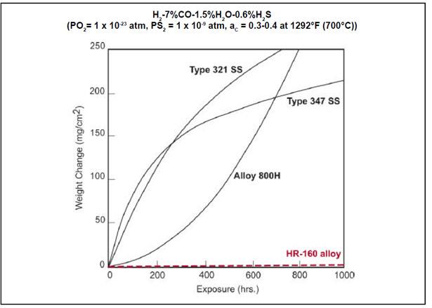
High temperature Corrosion Resistance
Sulfidation in Reducing Atmospheres
Ar – 5%H2 – 5%CO – 1%CO2 – 0.15%H2S (Vol. %) (PO2 = 3 x 10-19 atm, PS2 = 0.9 x 10⁻⁶ atm)

| 1600°F (871°C)/500 hours | |||||||
| Alloy | Cobalt | Metal Loss | Max. Depth of Attack | Average Depth of Attack | |||
| - | % | mils | mm | mils | mm | mils | mm |
| 6B | 57 | 0.3 | 0.008 | 3.1 | 0.08 | 3.3 | 0.08 |
| HR-160® | 30 | 0.2 | 0.005 | 5.2 | 0.13 | 5.7 | 0.14 |
| 25 | 51 | 4.1 | 0.10 | 8.4 | 0.21 | 14.6 | 0.37 |
| 188 | 39 | 7.6 | 0.10 | 14.9 | 0.38 | 23.6 | 0.60 |
| 150 | 50 | 10.3 | 0.26 | 22.1 | 0.56 | 28.3 | 0.72 |
| 556® | 18 | 20.6 | 0.52 | 31.9 | 0.81 | 35.6 | 0.90 |
Sulfidation in Reducing Atmospheres
|
H2-46%CO-0.8%CO-1.7%HS
Total Depth Attack |
||||
| Alloy | 1100°F (593°C) | 1300°F (704°C) | ||
| - | mpy | mm/y | mpy | mm/y |
| HR-160® | 14.4 | 0.37 | 27.3 | 0.70 |
| 6B | 23.6 | 0.60 | 264.4 | 6.72 |
| 150 | 37.7 | 0.96 | 108.8 | 2.76 |
| 25 | 94.1 | 2.39 | 188.5 | 4.79 |
| 188 | 150.5 | 3.82 | 292.6 | 7.43 |
| 556® | 121.1 | 3.08 | 345.8 | 8.78 |
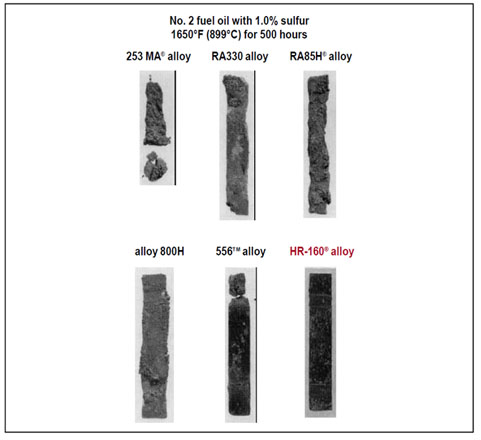
Sulfate-Induced Sulfidation in Combustion Atmospheres
Laboratory Hot Corrosion Burner Rig Testing – Specimens were exposed to a combustion stream generated in a burner rig fired with No. 2 fuel oil with a constant injection of 50 ppm (by weight) salt (mostly sodium chloride) into the combustion stream. Specimens were also subjected to thermal cycling by cycling them out of the test chamber once every hour and rapid fan cooling to less than 390°F (199°C) for two minutes.

Oxidation Resistance
Oxidation in Air
Laboratory tests were conducted in flowing air at 1800 to 2200°F (982 to 1204°C) for 1008 hours, with specimens cycled to room temperature once every 168 hours.
| Alloy | 1800°F (982°C) | 1800°F (982°C) | 1800°F (982°C) | 1800°F (982°C) | ||||||||||||
| Metal Loss | Average Metal Affected | Metal Loss | Average Metal Affected | Metal Loss | Average Metal Affected | Metal Loss | Average Metal Affected | |||||||||
| mils | μm | mils | μm | mils | μm | mils | μm | mils | μm | mils | μm | mils | μm | mils | μm | |
| HR-160® | 0.7 | 18 | 5.5 | 140 | 1.7 | 43 | 10.3 | 262 | 2.5 | 64 | 16.0 | 406 | 3.6 | 91 | 22.0 | 559 |
| 800HT | 0.0 | 0 | 4.1 | 104 | 7.6 | 193 | 11.6 | 295 | 11.0 | 279 | 15.0 | 381 | 19.4 | 493 | >58 | >1473 |
| 253MA | 1.3 | 33 | 3.0 | 76 | 0.7 | 18 | 8.2 | 208 | 8.7 | 221 | 16.5 | 419 | 18.6 | 472 | 29.2 | 742 |
| RA85H | 0.5 | 13 | 8.2 | 208 | 2.9 | 74 | 25.9 | 658 | 3.7 | 94 | >59 | >1499 | 3.9 | 99 | >59 | >1499 |
Long-Term Oxidation in Air
Laboratory tests were conducted at 2000°F (1093°C) in still air (box furnace), with specimens being cycled to room temperature once every 30 days.
| Alloy | 1800°F (982°C) | 1800°F (982°C) | 1800°F (982°C) | 1800°F (982°C) | ||||||||||||
| Metal Loss | Average Metal Affected | Metal Loss | Average Metal Affected | Metal Loss | Average Metal Affected | Metal Loss | Average Metal Affected | |||||||||
| mils | μm | mils | μm | mils | μm | mils | μm | mils | μm | mils | μm | mils | μm | mils | μm | |
| HR-160® | 2.5 | 64 | 16.7 | 424 | 3.6 | 91 | 29.0 | 737 | 7.6 | 193 | 58.7 | 1491 | 16.7 | 4204 | 26.3 | 668 |
| 601 | 0.5 | 13 | 22.4 | 569 | 5.4 | 137 | 45.1 | 1146 | 12.6 | 320 | 72.8 | 1849 | 27.3 | 693 | 38.9 | 988 |
| RA85H | 6.3 | 160 | 53.7 | 1364 | 17.9 | 455 | 80.3 | 2040 | 20.0 | 508 | 94.8 | 2408 | >251.7 | >6393 | >251.7 | >6393 |
| 800HT | 20.7 | 526 | 79.8 | 2027 | 44.3 | 1125 | 51.0 | 1295 | 65.2 | 1656 | 70.3 | 1786 | >249.9 | >6373 | >249.9 | >6373 |
Plate exposed for 360 days ( 8,640 hours) in still air, except for 1800°F test, which was exposed for 720 days (17,280 hours). Cycled once per month.
| Alloy | 1800°F (982°C) | 1800°F (982°C) | 1800°F (982°C) | 1800°F (982°C) | ||||||||||||
| Metal Loss | Average Metal Affected | Metal Loss | Average Metal Affected | Metal Loss | Average Metal Affected | Metal Loss | Average Metal Affected | |||||||||
| mils | μm | mils | μm | mils | μm | mils | μm | mils | μm | mils | μm | mils | μm | mils | μm | |
| HR-160® | 1.2 | 30 | 12.0 | 305 | 2.7 | 69 | 27.9 | 709 | 5.3 | 135 | 44.6 | 1133 | 8.9 | 226 | >250.0 | >6350 |
| 601 | 0.0 | 0 | 2.6 | 66 | 3.4 | 86 | 10.5 | 267 | 5.3 | 135 | 14.6 | 371 | 10.3 | 262 | 23.9 | 607 |
| RA85H | 0.7 | 18 | 14.6 | 371 | 8.9 | 226 | 14.3 | 363 | 6.4 | 163 | >250.0 | >6350 | 8.4 | 213 | >250.0 | >6350 |
| 800HT | 4.6 | 117 | 14.1 | 358 | 22.2 | 564 | 27.9 | 709 | 43.9 | 1115 | 48.9 | 1242 | 65.6 | 1666 | >250.0 | >6350 |
Plate exposed for 360 days ( 8,640 hours) in still air. Cycled once every two months.
Metallographic Technique used for Evaluating Environmental Tests

Chloridation Resistance
High-temperature Chloride Vapor Corrosion
Ar-20%O2-2%H2O-0.05%NaCl (Vol.%) 1830°F (999°C) for 75 hours
| Alloy | Total Depth Of Attack | |||
| mils | mm | |||
| 214® | 11.5 | 0.29 | ||
| HR 160® | 12.0 | 0.31 | ||
| 800H | >62.0 (complete penetration) | |||
Exposure to Chloride Vapors at 1600°F (871°C)

Chlorination Resistance

Carburization Resistance
Laboratory pack carburization testing in graphite at 1800°F (982°C) for 500 hours
| Alloy | Carbon Absorption | Total Depth Of Attack | ||
|
(mg/cm2) |
mils | mm | ||
| HR-120® | 0.0 | 0 | - | |
| 556® | 0.0 | 0 | - | |
| HR 160® | 0.3 | 0 | - | |
| 800HT | 0.3 | 0.9 | 0.02 | |
| 601 | 1.0 | 0.46 | 18.0 | |
| RA330 | 1.9 | 1.79 | 70.6 | |
| 310SS | 7.7 | 2.14 | 84.2 | |
| 253 MA | 11.6 | 2.34 | 92.1 | |
Exposure to Carbon Bed at 1650°F (899°C)

Ar-5%H-1%CH (Vol.%) 1800ºF (982ºC) for 55 hours
| Alloy | Carbon Absorption (mg/cm) |
| HR-160® | 2.9 |
| 601 | 3.2 |
| 800H | 3.6 |
| 600 | 7.3 |
| HR-120® | 7.9 |
| 556® | 7.9 |
| RA330 | 9.2 |
| 253 MA | 9.4 |
| 310 SS | 10.0 |
Nitridation Resistance
HAYNES® HR-160® alloy is also very resistant to nitridation attack. Tests were performed in flowing ammonia or nitrogen at various temperatures for 168 hours. Nitrogen absorption was determined by chemical analysis of samples before and after exposure and knowledge of the exposed specimen area.
Ammonia (NH3) 168 hours. Nitrogen Absorption (mg/cm2)
| Alloy | 1200°F (649°C) | 1800°F (982°C) | 2000°F (1093°C) |
| HR-160® | 0.9 | 2.2 | 3.0 |
| 601 | 1.1 | 1.2 | 2.6 |
| RA330 | 4.7 | 3.9 | 3.1 |
| 800H | 4.3 | 4.0 | 5.5 |
| 304 SS | 9.8 | 7.3 | 3.5 |
| 316 SS | 6.9 | 6.0 | 3.3 |
| 310 SS | 7.4 | 7.7 | 9.5 |
| 446 SS | 28.8 | 12.9 | 4.5 |
| 253 MA | - | 3.3 | 6.3 |
Nitrogen (N2) 2000°F (1093°C), 168 hours
| Alloy |
Nitrogen Absoption (mg/cm2) |
| HR-160® | 3.9 |
| 601 | 7.2 |
| RA330 | 6.6 |
| RA85H | 8.5 |
| 253 MA | 10.0 |
| 800H | 10.3 |
| 800HT | 11.4 |
| 310 SS | 12.3 |
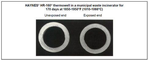
Waste Incineration Environments
Incineration of municipal, industrial and hazardous wastes generates very corrosive environments which typically contain such corrosive constituents as SO2, HCl and sometimes HF, along with vapors/deposits of chlorides and sulfates. The following examples demonstrate the relative improvements resulting from upgrading to HR-160® alloy.


Tensile Properties
Tensile Data (plate)*
| Test Temperature | Yield Strength 0.2% Offset | Ultimate Tensile Strength | Elongation | Reduction of Area | |||
| °F | °C | ksi | MPa | ksi | MPa | % | % |
| 70 | 21 | 45.6 | 314 | 111.2 | 767 | 68 | 73 |
| 200 | 93 | 40.4 | 279 | 104.0 | 717 | 69 | 74 |
| 400 | 204 | 33.8 | 233 | 97.9 | 675 | 71 | 74 |
| 600 | 316 | 27.6 | 190 | 91.9 | 634 | 74 | 70 |
| 800 | 427 | 26.0 | 179 | 87.7 | 605 | 76 | 68 |
| 1000 | 538 | 25.5 | 176 | 81.8 | 564 | 76 | 69 |
| 1200 | 649 | 25.7 | 177 | 75.8 | 523 | 70 | 67 |
| 1400 | 760 | 24.7 | 170 | 62.1 | 428 | 73 | 64 |
| 1600 | 871 | 22.1 | 152 | 38.3 | 264 | 85 | 84 |
| 1800 | 982 | 10.8 | 74 | 20.4 | 140 | 90 | 98 |
| 2000 | 1093 | 5.0 | 34 | 10.8 | 74 | 88 | 98 |
| 2100 | 1149 | 2.3 | 16 | 6.0 | 41 | 113 | 94 |
| 2200 | 1204 | 1.6 | 11 | 4.4 | 30 | 110 | 94 |
*Hot-Rolled and Solution-annealed
Tensile Data (Sheet)*
| Test Temperature | Yield Strength 0.2% Offset | Ultimate Tensile Strength | Elongation | |||
| °F | °C | ksi | MPa | ksi | MPa | % |
| 70 | 21 | 51.2 | 353 | 110.0 | 758 | 63 |
| 1000 | 538 | 32.7 | 225 | 82.5 | 569 | 73 |
| 1200 | 649 | 31.2 | 215 | 75.3 | 519 | 62 |
| 1400 | 760 | 30.7 | 212 | 61.1 | 421 | 47 |
| 1600 | 871 | 15.9 | 110 | 34.9 | 241 | 41 |
| 1800 | 982 | 9.5 | 66 | 18.7 | 129 | 51 |
| 2000 | 1093 | 4.7 | 32 | 9.8 | 68 | 53 |
| 2100 | 1149 | 2.8 | 19 | 6.6 | 46 | 107 |
| 2200 | 1204 | 2.0 | 14 | 4.8 | 33 | 91 |
*Solution-annealed
Creep and Stress Rupture Strengths
Plate- 2050°F (1121°C) Solution-anneal
| Test Temperature | Creep | Approximate Initial Stress to Produce Specified Creep in: | ||||||||
| 100 h | 10,000 h | 100 h | 10,000 h | |||||||
| °F | °C | % | ksi | MPa | ksi | MPa | ksi | MPa | ksi | MPa |
| 1100 | 593 | 1.0 | 29.4 | 203 | 20.4 | 141 | 14.4* | 100 | - | - |
| - | - | Rupture | 45.5 | 315 | 32.2 | 223 | 22.9 | 158 | 16.3 | 133 |
| 1200 | 649 | 1.0 | 18.9 | 131 | 12.1 | 91 | 9.3* | 64 | - | - |
| - | - | Rupture | 32.2 | 223 | 22.4 | 154 | 15.6 | 108 | 11.0 | 76 |
| 1300 | 704 | 1.0 | 12.5 | 86 | 8.7 | 60 | 6.2* | 43 | - | - |
| - | - | Rupture | 22.9 | 158 | 15.7 | 108 | 10.8 | 75 | 7.4 | 51 |
| 1400 | 760 | 1.0 | 8.5 | 59 | 6.0 | 41 | 4.2* | 29 | - | - |
| - | - | Rupture | 16.4 | 113 | 11.0 | 76 | 7.4 | 51 | 5.0 | 34 |
| 1500 | 816 | 1.0 | 5.9 | 41 | 4.1 | 28 | 2.9* | 20 | - | - |
| - | - | Rupture | 11.7 | 81 | 7.7 | 53 | 5.1 | 35 | 3.4 | 23 |
| 1600 | 871 | 1.0 | 4.2 | 29 | 2.9 | 20 | 2.1* | 14 | - | - |
| - | - | Rupture | 8.4 | 58 | 5.5 | 38 | 3.6 | 25 | 2.4 | 17 |
| 1700 | 927 | 1.0 | 3.0 | 21 | 2.1 | 14 | 1.5* | 10 | - | - |
| - | - | Rupture | 6.1 | 42 | 3.9 | 27 | 2.5 | 17 | 1.6 | 11 |
| 1800 | 982 | 1.0 | 2.2 | 15 | 1.5 | 10 | 1.1* | 8 | - | - |
| - | - | Rupture | 4.4 | 30 | 2.8 | 19 | 1.8 | 12 | 1.2 | 8 |
*Extrapolation
Sheet, Solution-annealed
| Temperature | Creep | Approximate Initial Stress to Produce Specified Creep in | ||||
| 100 Hours | 100 Hours | |||||
| °F | °C | % | ksi | MPa | ksi | MPa |
| 1200 | 649 | 0.5 | 16 | 110 | 12.5 | 86 |
| 1 | 18.5 | 128 | 15 | 103 | ||
| R | 28 | 193 | 20 | 138 | ||
| 1300† | 704 | 0.5 | 11.5 | 79 | 9.2 | 63 |
| 1 | 13.9 | 96 | 10.8 | 74 | ||
| R | 19 | 131 | 14.5 | 100 | ||
| 1400 | 760 | 0.5 | 8.5 | 59 | 6.8* | 47* |
| 1 | 9.9 | 68 | 8.2* | 57* | ||
| R | 13 | 90 | 9.9 | 68 | ||
| 1500 | 816 | 0.5 | 6.2 | 43 | 4.9* | 34* |
| 1 | 8.2 | 57 | 6.0* | 41* | ||
| R | 9.6 | 66 | 7.9 | 54 | ||
| 1600 | 871 | 0.5 | 4.7 | 32 | 3.4* | 23* |
| 1 | 5.2 | 36 | 4.3* | 30* | ||
| R | 6.8 | 47 | 5.1 | 35 | ||
| 1700 | 927 | 0.5 | 3.2 | 22 | 2.1* | 14* |
| 1 | 3.6 | 25 | 2.7* | 19* | ||
| R | 4.6 | 32 | 3.2 | 22 | ||
| 1800 | 982 | 0.5 | 2.1 | 14 | 1.2 | 8.3 |
| 1 | 2.7 | 19 | 1.6 | 11 | ||
| R | 3.5 | 24 | 2.6 | 18 | ||
*Significant extrapolation
† Values obtained using Larson-Miller interpolation
Comparative Stress-Rupture Strengths
| Test Temperature | 10,000 Hour Rupture Strengths (ksi*) | ||||||||
| °F | °C | HR-160® | RA333® | 800HT | RA330® | 253 MA | RA85H | 309 | 310 |
| 1200 | 649 | 15.6 | 16.5 | 17.5 | 11.0 | 14.0 | 12.0 | 16.0 | 9.3 |
| 1300 | 704 | 10.8 | 12.0 | 11.0 | - | 8.5 | - | - | - |
| 1400 | 760 | 7.4 | 9.2 | 7.3 | 4.3 | 5.2 | 5.0 | 5.45 | 3.9 |
| 1500 | 816 | 5.1 | 5.7 | 5.2 | - | 3.75 | - | - | - |
| 1600 | 871 | 3.6 | 3.1 | 3.5 | 1.7 | 2.5 | 2.1 | 1.86 | 1.65 |
| 1700 | 927 | 2.5 | 1.8 | 1.9 | - | 1.65 | - | - | - |
| 1800 | 982 | 1.8 | 1.05 | 1.2 | 0.63 | 1.15 | 0.9 | 0.63 | 0.69 |
*ksi can be converted to MPa (megapascals) by multiplying 6.895.
**Extrapolation.
Physical Properties
| Physical Property | British Units | Metric Units | ||
| Density | RT |
0.292 lb/in3 |
RT |
8.08 g/cm3 |
| Electrical Resistivity | RT | 43.8 µohm.in | RT | 111.2 µohm.cm |
| 200°F | 44.3 µohm.in | 100°C | 112.8 µohm.cm | |
| 400°F | 45.2 µohm.in | 200°C | 114.7 µohm.cm | |
| 600°F | 46.1 µohm.in | 300°C | 116.7 µohm.cm | |
| 800°F | 46.9 µohm.in | 400°C | 118.6 µohm.cm | |
| 1000°F | 47.8 µohm.in | 500°C | 120.6 µohm.cm | |
| 1200°F | 48.3 µohm.in | 600°C | 122.4 µohm.cm | |
| 1400°F | 48.6 µohm.in | 700°C | 123.1 µohm.cm | |
| 1600°F | 48.9 µohm.in | 800°C | 123.8 µohm.cm | |
| 1800°F | 49.3 µohm.in | 900°C | 124.5 µohm.cm | |
| 2000°F | 49.6 µohm.in | 1000°C | 125.2 µohm.cm | |
| 2200°F | 49.9 µohm.in | 1100°C | 125.9 µohm.cm | |
| - | - | 1200°C | 126.7 µohm.cm | |
| Thermal Diffusivity | RT |
4.6 x 10⁻³ in2/s |
RT |
29.4 x 10⁻³ cm2/s |
| 200°F |
4.8 x 10⁻³ in2/s |
100°C |
30.8 x 10⁻³ cm2/s |
|
| 400°F |
5.2 x 10⁻³ in2/s |
200°C |
33.6 x 10⁻³ cm2/s |
|
| 600°F |
5.8 x 10⁻³ in2/s |
300°C |
37.0 x 10⁻³ cm2/s |
|
| 800°F |
6.4 x 10⁻³ in2/s |
400°C |
40.6 x 10⁻³ cm2/s |
|
| 1000°F |
7.0 x 10⁻³ in2/s |
500°C |
44.3 x 10⁻³ cm2/s |
|
| 1200°F |
7.2 x 10⁻³ in2/s |
600°C |
45.6 x 10⁻³ cm2/s |
|
| 1400°F |
7.4 x 10⁻³ in2/s |
700°C |
47.2 x 10⁻³ cm2/s |
|
| 1600°F |
7.5 x 10⁻³ in2/s |
800°C |
48.6 x 10⁻³ cm2/s |
|
| 1800°F |
7.8 x 10⁻³ in2/s |
900°C |
48.7 x 10⁻³ cm2/s |
|
| 2000°F |
8.4 x 10⁻³ in2/s |
1000°C |
50.9 x 10⁻³ cm2/s |
|
| 2200°F |
8.8 x 10⁻³ in2/s |
1100°C |
54.1 x 10⁻³ cm2/s |
|
| - | - | 1200°C |
56.1 x 10⁻³ cm2/s |
|
| Thermal Conductivity | RT |
75 Btu.in/h.ft2.°F |
RT | 10.9 W/m-°C |
| 200°F |
82 Btu.in/h.ft2.°F |
100°C | 12.0 W/m-°C | |
| 400°F |
95 Btu.in/h.ft2.°F |
200°C | 13.6 W/m-°C | |
| 600°F |
108 Btu.in/h.ft2.°F |
300°C | 15.4 W/m-°C | |
| 800°F |
126 Btu.in/h.ft2.°F |
400°C | 17.6 W/m-°C | |
| 1000°F |
144 Btu.in/h.ft2.°F |
500°C | 19.9 W/m-°C | |
| 1200°F |
162 Btu.in/h.ft2.°F |
600°C | 21.8 W/m-°C | |
| 1400°F |
178 Btu.in/h.ft2.°F |
700°C | 24.7 W/m-°C | |
| 1600°F |
185 Btu.in/h.ft2.°F |
800°C | 26.1 W/m-°C | |
| 1800°F |
196 Btu.in/h.ft2.°F |
900°C | 26.9 W/m-°C | |
| 2000°F |
213 Btu.in/h.ft2.°F |
1000°C | 28.7 W/m-°C | |
| 2200°F |
228 Btu.in/h.ft2.°F |
1100°C | 31.1 W/m-°C | |
| - | - | 1200°C | 32.9 W/m-°C | |
| Specific Heat | RT | 0.110 Btu/lb.°F | RT | 462 J/kg-°C |
| 200°F | 0.116 Btu/lb.°F | 100°C | 487 J/kg-°C | |
| 400°F | 0.121 Btu/lb.°F | 200°C | 506 J/kg-°C | |
| 600°F | 0.125 Btu/lb.°F | 300°C | 521 J/kg-°C | |
| 800°F | 0.131 Btu/lb.°F | 400°C | 542 J/kg-°C | |
| 1000°F | 0.136 Btu/lb.°F | 500°C | 562 J/kg-°C | |
| 1200°F | 0.151 Btu/lb.°F | 600°C | 597 J/kg-°C | |
| 1400°F | 0.159 Btu/lb.°F | 700°C | 653 J/kg-°C | |
| 1600°F | 0.165 Btu/lb.°F | 800°C | 672 J/kg-°C | |
| 1800°F | 0.167 Btu/lb.°F | 900°C | 689 J/kg-°C | |
| 2000°F | 0.171 Btu/lb.°F | 1000°C | 704 J/kg-°C | |
| 2200°F | 0.175 Btu/lb.°F | 1100°C | 719 J/kg-°C | |
| - | - | 1200°C | 732 J/kg- | |
| Mean Coefficient of Thermal Expansion | 78-200°F | 7.2 µin/in-°F | 25-100°C | 13.0 µm/m-°C |
| 78-400°F | 7.6 µin/in-°F | 25-200°C | 13.7 µm/m-°C | |
| 78-600°F | 7.9 µin/in-°F | 25-300°C | 14.0 µm/m-°C | |
| 78-800°F | 8.1 µin/in-°F | 25-400°C | 14.4 µm/m-°C | |
| 78-1000°F | 8.3 µin/in-°F | 25-500°C | 14.9 µm/m-°C | |
| 78-1200°F | 8.6 µin/in-°F | 25-600°C | 15.5 µm/m-°C | |
| 78-1400°F | 8.9 µin/in-°F | 25-700°C | 15.7 µm/m-°C | |
| 78-1600°F | 9.2 µin/in-°F | 25-800°C | 16.6 µm/m-°C | |
| 78-1800°F | 9.5 µin/in-°F | 25-900°C | 17.1 µm/m-°C | |
| Dynamic Modulus of Elasticity | RT |
30.6 x 10⁶ psi |
RT | 211 GPa |
| 100°F |
30.5 x 10⁶ psi |
50°C | 210 GPa | |
| 200°F |
30.1 x 10⁶ psi |
100°C | 207 GPa | |
| 300°F |
29.6 x 10⁶ psi |
150°C | 204 GPa | |
| 400°F |
29.1 x 10⁶ psi |
200°C | 201 GPa | |
| 500°F |
28.6 x 10⁶ psi |
250°C | 198 GPa | |
| 600°F |
27.8 x 10⁶ psi |
300°C | 193 GPa | |
| 700°F |
27.1 x 10⁶ psi |
350°C | 189 GPa | |
| 800°F |
26.5 x 10⁶ psi |
400°C | 185 GPa | |
| 900°F |
26.1 x 10⁶ psi |
450°C | 182 GPa | |
| 1000°F |
25.6 x 10⁶ psi |
500°C | 179 GPa | |
| 1100°F |
25.1 x 10⁶ psi |
550°C | 176 GPa | |
| 1200°F |
24.4 x 10⁶ psi |
600°C | 173 GPa | |
| 1300°F |
23.7 x 10⁶ psi |
650°C | 168 GPa | |
| 1400°F |
22.9 x 10⁶ psi |
700°C | 163 GPa | |
| 1500°F |
22.4 x 10⁶ psi |
750°C | 159 GPa | |
| 1600°F |
21.7 x 10⁶ psi |
800°C | 155 GPa | |
| 1700°F |
21.1 x 10⁶ psi |
850°C | 151 GPa | |
| 1800°F |
19.8 x 10⁶ psi |
900°C | 147 GPa | |
| - | - | 950°C | 266 GPa | |
RT= Room Temperature
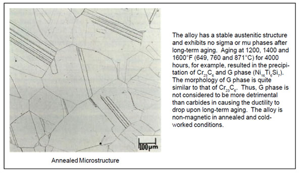
Physical Metallurgy
| - | Typical Grain Size | Average Hardness |
| Plate | 3 - 4½ | 89 |
| Bar | 2 - 3 | 85 |
| Sheet | 3½ - 4½ | 88 |
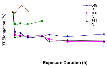
Thermal Stability
| Exposure Temperature | Exposure Duration | 0.2% Yield strength | Ultimate Tensile Strength | 4D Elongation | AGL* Elongation | RA | Impact energy | ||||
| °F | °C | h | ksi | MPa | ksi | MPa | % | % | % | ft-lb | J |
| - | - | 0 | 49 | 338 | 119.7 | 825 | 64.1 | 59.6 | 70.6 | 263 | 357 |
| 1200 | 649 | 1000 | 51.5 | 355 | 123.6 | 852 | 32.2 | 32.8 | 28.8 | 29 | 39 |
| 1200 | 649 | 4000 | 54.5 | 376 | 131.4 | 906 | 30.2 | 30 | 26.4 | 27 | 36 |
| 1200 | 649 | 8000 | 54.7 | 377 | 130.4 | 899 | 23.1 | 22.8 | 20 | 23 | 31 |
| 1200 | 649 | 16000 | 55.3 | 381 | 135.8 | 936 | 24.7 | 23.4 | 20.8 | 21 | 28 |
| 1200 | 649 | 20000 | 53.7 | 370 | 129.1 | 890 | 27.4 | 27.1 | 24.6 | 26 | 35 |
| 1200 | 649 | 30000 | 53.5 | 369 | 131.3 | 905 | 24.7 | 24.2 | 23.7 | 22 | 30 |
| 1200 | 649 | 50000 | 53.8 | 371 | 134.5 | 927 | 28.3 | 26.4 | 22.1 | 21 | 29 |
| 1400 | 760 | 1000 | 50.8 | 350 | 131.1 | 904 | 26.8 | 26.9 | 22.2 | 24 | 33 |
| 1400 | 760 | 4000 | 50.6 | 349 | 131.1 | 904 | 26.3 | 26.1 | 26 | 21 | 28 |
| 1400 | 760 | 8000 | 50 | 345 | 130.1 | 897 | 24.8 | 25.1 | 22.5 | 19 | 26 |
| 1400 | 760 | 16000 | 49.9 | 344 | 130.7 | 901 | 24.6 | 25 | 21.2 | 19 | 26 |
| 1400 | 760 | 20000 | 43.7 | 301 | 107.9 | 744 | 20.2 | 19.3 | 14 | 12 | 16 |
| 1400 | 760 | 30000 | 44.7 | 308 | 102.4 | 706 | - | 16.4 | 11.3 | 10 | 14 |
| 1400 | 760 | 50000 | 43.5 | 300 | 102.3 | 705 | - | 16.2 | 12.4 | 10 | 13 |
| 1600 | 871 | 1000 | 45.7 | 315 | 114.6 | 790 | 23.2 | 23.8 | 20.8 | 17 | 23 |
| 1600 | 871 | 4000 | 44.5 | 307 | 114 | 786 | 24.8 | 25.1 | 20.5 | 17 | 23 |
| 1600 | 871 | 8000 | 44.7 | 308 | 114.9 | 792 | 24.8 | 25.3 | 22.6 | 15 | 21 |
| 1600 | 871 | 16000 | 44.4 | 306 | 115 | 793 | 25.2 | 25.9 | 22.2 | 16 | 22 |
| 1600 | 871 | 20000 | 41 | 283 | 88.6 | 611 | 17 | 17.2 | 15.1 | 6 | 8 |
| 1600 | 871 | 30000 | 41.6 | 287 | 89.9 | 620 | 18.3 | 18.1 | 15.3 | 7 | 10 |
| 1600 | 871 | 50000 | 40.9 | 282 | 86.2 | 594 | 17.4 | 17.6 | 14.5 | 8 | 11 |
| 1800 | 982 | 1000 | 43.9 | 303 | 119.1 | 821 | 44.6 | 44.9 | 39 | 49 | 66 |
| 1800 | 982 | 4000 | 43.7 | 301 | 117.5 | 810 | 45.3 | 44.5 | 39.2 | 46 | 63 |
| 1800 | 982 | 8000 | 43.2 | 298 | 115.3 | 795 | 44.4 | 43.6 | 38 | 44 | 59 |
| 1800 | 982 | 16000 | 43.4 | 299 | 114.3 | 788 | 49.4 | 48.5 | 42 | 54 | 73 |
| 2000 | 1093 | 1000 | 38.4 | 265 | 104.4 | 720 | 62.3 | 64.3 | 62.8 | 264 | 358 |
| 2000 | 1093 | 5065 | 37.6 | 259 | 99.5 | 686 | 74 | 72.1 | 65.4 | 263 | 357 |
| 2000 | 1093 | 8000 | 37.6 | 259 | 100.2 | 691 | 64.6 | 67.1 | 60.1 | 264 | 358 |
*AGL is adjusted gauge length and AGL % elongation is useful when tensile fracture
RA= Reduction of Area


Aqueous Corrosion Resistance
Stress Corrosion Cracking
| Alloy | Time to Failure, h | |
| HR-160® | 1000 | No Cracking |
| C-22® | 1000 | No Cracking |
| 825 | 150 | Cracked |
| 316L SS | 24 | Cracked |
Uniform Corrosion
| – | Average Corrosion Rate, mm/y* | ||
| HR-160® | 625 | 316L SS | |
|
3% HCl + 59% HNO3, 80°C |
2 | 20 | – |
|
1% HF + 20% HNO3, 80°C |
35 | 123 | >400 |
|
50% H2SO4 + 10% HNO3, Boiling |
20 | – | – |
|
60% H2SO4 + 5% HNO3, Boiling |
50 | 105 | – |
|
65% HNO3, Boiling |
9 | 20 | 12 |
|
50% H2SO4 + 42 g/l Fe2 (SO4)3 G-28A, Boiling |
9 | 24 | 38 |
|
25% H2SO4 + 5% HNO3 + 4% NaCl, Boiling |
3 | 713 | – |
| 1% HCl, Boiling | 469 | 0.9 | 524 |
|
1% HCl + 1% H2SO4 + 1% HF, 79°C |
107 | 120 | 245 |
*To convert mils per year (mpy) to mm per year, divide by 40.
Welding
HAYNES® HR-160® alloy is readily weldable by Gas Tungsten Arc (TIG) and Gas Metal Arc (MIG) welding processes. Many of the alloy’s welding characteristics are similar to those for the HASTELLOY® alloys and the same precautions apply. Submerged arc welding is not recommended as this process is characterized by high heat input which could result in distortion and hot cracking. HR-160® filler metal is prone to start/stop cracking. The filler metal may be prone to hot cracking when welding heavy plate (e.g. greater than 1/2 inch thick) under highly restrained conditions. Any localized cracking should be removed by grinding prior to further welding. Do not attempt to remelt or “wash-out” welding cracks.
Base Metal Preperation
The joint surface and adjacent area should be thoroughly cleaned before welding. All grease, oil, crayon marks, sulfur compounds and other foreign matter should be removed. It is preferable, but not mandatory, that the alloy be in the solution-annealed condition when welded.
Filler Metal Selection
Matching composition filler metal is recommended for joining HR-160® alloy. When dissimilar base metals are to be jointed, such as HR-160® alloy to a stainless steel, HAYNES 556® filler metal is recommended. Please click here or see the Haynes Welding SmartGuide for more information.
Preheating, Interpass Temperatures and Postweld Heat Treatment
Preheat should not be used so long as the base metal to be welded is above 32°F (0°C). Interpass temperatures should be less than 200°F (93°C). Auxiliary cooling methods may be used between weld passes, as needed, providing that such methods do not introduce contaminants. Postweld heat treatment is not normally required for HR-160® alloy.
Nominal Welding Parameters
Nominal welding parameters are provided as a guide for performing typical operations. These are based on welding conditions used in our laboratory and should be considered only as a guideline. For further information, please click here.


AWM Tensile
| Type | Test Temperature | Ultimate Tensile Strength | 0.2% Yield Strength | Elongation | |||
| °F | °C | ksi | MPa | ksi | MPa | % | |
| GMAW | RT | RT | 94.1 | 649 | 58.0 | 400 | 26.4 |
| 500 | 260 | 81.9 | 565 | 45.8 | 316 | 25.2 | |
| 1000 | 538 | 71.3 | 492 | 42.8 | 295 | 32.4 | |
| 1400 | 760 | 43.2 | 298 | 33.7 | 232 | 29.6 | |
| 1600 | 871 | 22.7 | 157 | 17.6 | 121 | 33.3 | |
| GTAW | RT | RT | 101.3 | 698 | 68.5 | 472 | 26.4 |
| 500 | 260 | 81.7 | 563 | 47.2 | 325 | 32.1 | |
| 1000 | 538 | 70.4 | 485 | 42.8 | 295 | 43.7 | |
| 1400 | 760 | 46.3 | 319 | 34.4 | 237 | 30.0 | |
| 1600 | 871 | 22.6 | 156 | 18.1 | 125 | 72.2 | |
All-Weld Metal samples
RT= Room Temperature
Welded Transverse Tensile
| Condition | Test Temperature | Ultimate Tensile Strength | 0.2% Yield Strength | Elongation | |||
|---|---|---|---|---|---|---|---|
| °F | °C | ksi | MPa | ksi | MPa | % | |
| As-Welded | RT | RT | 102.3 | 705 | 60.1 | 414 | 30.6 |
| 500 | 260 | 82.9 | 572 | 49.5 | 341 | 32.0 | |
| 1000 | 538 | 75.3 | 519 | 47.1 | 325 | 39.5 | |
| 1400 | 760 | 45.4 | 313 | 31.3 | 216 | 26.3 | |
| 1600 | 871 | 23.6 | 163 | 18.6 | 128 | 33.9 | |
| Aged* | RT | RT | 98.7 | 680 | 52.8 | 364 | 18.1 |
GTAW welded transverse tensile samples
*Samples aged at 1600°F (871°C) for 1000 hours
RT= Room Temperature
Welded Creep Rupture
| Test Temperature | Stress | 1% Creep Life | 5% Creep Life | Rupture Life | Elongation | ||
|---|---|---|---|---|---|---|---|
| °F | °C | ksi | MPa | h | h | h | % |
| 1200 | 649 | 30.0 | 207 | 12.9 | 67.0 | 110.7 | 13.7 |
| 1400 | 760 | 18.0 | 124 | 5.0 | 13.1 | 29.2 | 22.0 |
| 1600 | 871 | 11.5 | 79 | 49.0 | 67.5 | 114.6 | 26.9 |
| 1700 | 927 | 6.0 | 41 | 61.0 | 94.0 | 152.4 | 33.9 |
Specifications and Codes
Specifications
| HAYNES® HR-160® alloy (N12160) | |
| Sheet, Plate & Strip | SB 435/B 435P= 46 |
| Billet, Rod & Bar | SB 572/B 572B 472P= 46 |
| Coated Electrodes | - |
| Bare Welding Rods & Wire | SFA 5.14/ A 5.14 (ERNiCoCrSi-1)F= 46 |
| Seamless Pipe & Tube | SB 622/B 622P= 46 |
| Welded Pipe & Tube | SB 619/B 619SB 626/B 626P= 46 |
| Fittings | SB 366/B 366P=46 |
| Forgings | SB 564/B 564P= 46 |
| DIN | No. 2.4880NiCo29Cr28Si |
| Others | - |
Codes
| HAYNES® HR-160® alloy (N12160) | |||
| ASME | Section l | - | |
| Section lll | Class 1 | - | |
| Class 2 | - | ||
| Class 3 | - | ||
| Section lV | HF-300.2 | - | |
| Section Vlll | Div. 1 |
1800°F (982°C)1,2 |
|
| Div. 2 | - | ||
| Section Xll | - | ||
| B16.5 | - | ||
| B16.34 | - | ||
| B31.1 | - | ||
| B31.3 | - | ||
1Plate, Sheet, Bar, Forgings, fittings, welded pipe/tube, seamless pipe/tube
2ASME Code Case No. 2385
Disclaimer
Haynes International makes all reasonable efforts to ensure the accuracy and correctness of the data displayed on this site but makes no representations or warranties as to the data’s accuracy, correctness or reliability. All data are for general information only and not for providing design advice. Alloy properties disclosed here are based on work conducted principally by Haynes International, Inc. and occasionally supplemented by information from the open literature and, as such, are indicative only of the results of such tests and should not be considered guaranteed maximums or minimums. It is the responsibility of the user to test specific alloys under actual service conditions to determine their suitability for a particular purpose.
For specific concentrations of elements present in a particular product and a discussion of the potential health affects thereof, refer to the Safety Data Sheets supplied by Haynes International, Inc. All trademarks are owned by Haynes International, Inc., unless otherwise indicated.
Alloy Brochure