HAYNES® 214® alloy
Principal Features
Excellent Oxidation Resistance
HAYNES® 214® alloy (UNS N07214) is a nickel – chromium-aluminum-iron alloy, developed to provide the optimum in high-temperature oxidation resistance for a wrought austenitic material, while at the same time allowing for conventional forming and joining. Intended principally for use at temperatures of 1750°F (955°C) and above, 214® alloy exhibits resistance to oxidation that far exceeds virtually all conventional heat-resistant wrought alloys at these temperatures. This is attributable to the formation of a tightly adherent Al2O3-type protective oxide scale, which forms in preference to chromium oxide scales at these high temperatures. At temperatures below 1750°F (955°C), 214® alloy develops an oxide scale which is a mixture of chromium and aluminum oxides. This mixed scale is somewhat less protective, but still affords 214® alloy oxidation resistance equal to the best nickel-base alloys. The higher temperature Al2O3 – type scale which 214® alloy forms also provides the alloy with excellent resistance to carburization, nitriding and corrosion in chlorine-bearing oxidizing environments.
Fabrication
HAYNES® 214® alloy, like many high aluminum content nickel-base alloys that are intended to be age-hardened by intermediate temperature heat treatment, will exhibit age-hardening as a result of the formation of a second phase, gamma prime (Ni3Al), if exposed at temperatures in the range of 1100 – 1700°F (595 – 925°C). As a consequence of this, 214® alloy is susceptible to strain-age cracking when highly stressed, highly-restrained, welded components are slowly heated through the intermediate temperature regime. The keys to avoiding this problem are to minimize weldment restraint through appropriate component design, and/or heat rapidly through the 1100 – 1700°F (595 – 925°C) temperature range during post-fabrication heat treatment (or first-use heat-up).
With the exception of the above consideration, HAYNES® 214® alloy does exhibit good forming and welding characteristics. It may be forged or otherwise hot-worked, providing it is held at 2100°F (1150°C) for a time sufficient to bring the entire piece to temperature. Its room temperature tensile ductility is also high enough to allow the alloy to be formed by cold working. All cold or hot-worked parts should be annealed and rapidly cooled in order to restore the best balance of properties.
The alloy can be welded by a variety of techniques, including gas tungsten arc (TIG), gas metal arc (MIG) or shielded metal arc (coated electrode) welding.
Heat-Treatment
HAYNES® 214® alloy is furnished in the solution heat-treated condition, unless otherwise specified. The alloy is normally solution heat-treated at 2000°F (1095°C) and rapidly cooled or quenched for optimum properties. Heat treating at temperatures below the solution heat-treating temperature will result in grain boundary carbide precipitation and, below 1750°F (955°C), precipitation of gamma prime phase. Such lower temperature age-hardening heat treatments are not suggested.
Applications
HAYNES® 214® alloy combines properties which make it very suitable for service in relatively low-stress, high temperature oxidizing environments, where the utmost in resistance to oxidation or scale exfoliation is needed. Its resistance to such environments persists to temperatures as high as 2400°F (1315°C), although strength limitations may apply. Applications can include “Clean Firing” uses such as mesh belts, trays and fixtures for firing of pottery and fine china, and the heat treatment of electronic devices and technical grade ceramics. In the gas turbine industry, 214® alloy is used for foil construction honeycomb seals, combustor splash plates, and other static oxidation – limited parts. The automotive industry has applications for 214® alloy in catalytic converter internals, and it is used as a burner cup material in auxiliary heaters for military vehicles. In the industrial heating market, 214® alloy is used for highly specialized applications such as refractory anchors, furnace flame hoods, and rotary calciners for processing chloride compounds. It is also used for parts in high temperature chlorine-contaminated environments, such as hospital waste incinerator internals.
*Please contact our technical support team if you have technical questions about this alloy.
Nominal Composition
| Weight % | |
| Nickel | 75 Balance |
| Chromium | 16 |
| Aluminum | 4.5 |
| Iron | 3 |
| Cobalt | 2 max. |
| Manganese | 0.5 max. |
| Molybdenum | 0.5 max. |
| Titanium | 0.5 max. |
| Tungsten | 0.5 max. |
| Niobium | 0.15 max. |
| Silicon | 0.2 max. |
| Zirconium | 0.1 max. |
| Carbon | 0.04 |
| Boron | 0.01 max. |
| Yttrium | 0.01 |
Applications

Oxidation Resistance
HAYNES® 214® alloy provides resistance to oxidation at temperatures of 1750°F (955°C) and above that is virtually unmatched by any other wrought heat-resistant alloy. It can be used for long-term continuous exposure to combustion gases or air at temperatures up to 2300°F (1260°C), and, for shorter term exposures, it can be used at even higher temperatures. Useful short-term oxidation resistance has even been demonstrated at temperatures as high as 2400°F (1315°C).
Comparative Oxidation Resistance in Flowing Air*
| Alloy | 1800°F (980°C)/1008 Hours | 2000°F (1095°C)/1008 Hours | 2100°F (1150°C)/1008 Hours | 2200°F (1205°C)/1008 Hours | ||||||||||||
| Average Metal Loss** | Average Metal Affected*** | Average Metal Loss** | Average Metal Affected*** | Average Metal Loss** | Average Metal Affected*** | Average Metal Loss** | Average Metal Affected*** | |||||||||
| mils | μm | mils | μm | mils | μm | mils | μm | mils | μm | mils | μm | mils | μm | mils | μm | |
| 214® | 0.1 | 3 | 0.3 | 8 | 0.1 | 3 | 0.2 | 5 | 0.1 | 3 | 0.5 | 13 | 0.1 | 3 | 0.7 | 18 |
| 230® | 0.2 | 5 | 1.5 | 38 | 0.5 | 13 | 3.3 | 84 | 1.2 | 30 | 4.4 | 112 | 4.7 | 119 | 8.3 | 211 |
| X | 0.2 | 5 | 1.5 | 38 | 1.3 | 33 | 4.4 | 112 | 3.6 | 91 | 6.1 | 115 | – | – | – | – |
| 601 | 0.4 | 10 | 1.7 | 43 | 1.3 | 33 | 3.8 | 97 | 2.8 | 71 | 6.5 | 165 | 4.4 | 112 | 7.5 | 191 |
| HR-120® | 0.4 | 10 | 2.1 | 53 | 1 | 25 | 4.4 | 112 | 7.9 | 201 | 10.1 | 257 | 21.7 | 551 | 25.4 | 645 |
| 556® | 0.4 | 10 | 2.3 | 58 | 1.5 | 38 | 6.9 | 175 | 10.4 | 264 | 17.5 | 445 | – | – | – | – |
| 600 | 0.3 | 8 | 2.4 | 61 | 0.9 | 23 | 3.3 | 84 | 2.8 | 71 | 4.8 | 122 | 5.1 | 130 | 8.4 | 213 |
| RA-330 | 0.3 | 8 | 3.0 | 76 | 0.8 | 20 | 6.7 | 170 | – | – | – | – | – | – | – | – |
| 800HT | 0.5 | 13 | 4.1 | 104 | 7.6 | 193 | 11.6 | 295 | 11 | 279 | 15.0 | 381 | – | – | – | – |
| HR-160® | 0.7 | 18 | 5.5 | 140 | 1.7 | 43 | 10.3 | 262 | 2.5 | 64 | 16.0 | 406 | 13.5 | 345 | 62.9 | 1598 |
| 304 SS | 5.5 | 140 | 8.1 | 206 | NA | NA | >19.6 | >498 | NA | NA | >19.5 | >495 | – | – | – | – |
| 316 SS | 12.3 | 312 | 14.2 | 361 | NA | NA | >17.5 | >445 | NA | NA | >17.5 | >445 | – | – | – | – |
| 446 SS | – | – | – | – | 13 | 330 | 14.4 | 366 | NA | NA | >21.5 | >546 | – | – | – | – |
*Flowing air at a velocity of 7.0 ft/min (213.4 cm/min) past the samples. Samples cycled to room temperature once per week.
** Metal loss was calculated from final and initial metal thicknesses; i.e. ML = (OMT – FMT) /2.
***Average Metal Affected is sum of Metal Loss and Average Internal Penetration.
Metallographic Technique used for Evaluating Environmental Tests

Comparative Oxidation in Flowing Air 2100°F (1150°C)
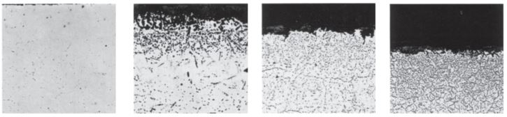
Microstructures shown are for coupons exposed for 1008 hours at 2100°F (1150°C) in air flowing at 7.0 feet/minute (213.4 cm/minute) past the samples. Samples were descaled by cathodically charging the coupons while they were immersed in a molten salt solution. The black area shown at the top of each picture represents actual metal loss due to oxidation. The data clearly show HAYNES® 214® alloy is only slightly affected by the exposure, while other nickel-chromium alloys, such as alloys 600 and 601, and iron-nickel-chromium alloys, such as RA330® alloy, all exhibit significantly more oxidation damage. Of particular importance is the almost total absence of internal attack for the 214 alloy. This contrasts markedly with the very substantial amount of internal attack evidenced by the alloy 601 and RA330 alloy tests coupons. The nature of this internal attack, as illustrated by the photomicrographs, is common for alloys containing 1-2% aluminum or silicon. Such levels of these elements do promote chromium oxide scale adherence, but do not afford improved resistance to oxide penetration below the scale.
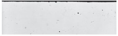
HAYNES® 214® alloy
Average Metal Affected
= 0.5 mils (13 µm)
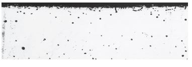
Alloy 600
Average Metal Affected
=4.8 mils (122µm)
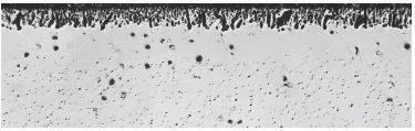
Alloy 601
Average Metal Affected
=6.5 mils (165 µm)
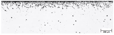
RA330 alloy
Average Metal Affected
=8.7 mils (221 µm)
Comparative Burner Rig Oxidation Resistance
| Alloy | 1800°F (980°C)/1008 Hours | 2000°F (1095°C)/1008 Hours | 2100°F (1150°C)/1008 Hours | |||||||||
| Metal Loss* | Average Metal Affected** | Metal Loss* | Average Metal Affected** | Metal Loss* | Average Metal Affected** | |||||||
| mils | µm | mils | µm | mils | µm | mils | µm | mils | µm | mils | µm | |
| 214® | 1.5 | 38 | 1.8 | 46 | 1.2 | 30 | 1.5 | 38 | 2.0 | 51 | 2.1 | 53 |
| 230® | 2.8 | 71 | 5.6 | 142 | 7.1 | 180 | 9.9 | 251 | 6.4 | 163 | 13.1 | 333 |
| 556® | 4.1 | 104 | 6.7 | 170 | 9.9 | 251 | 12.1 | 307 | 11.5 | 292 | 14 | 356 |
| X | 4.3 | 109 | 7.3 | 185 | 11.6 | 295 | 14.0 | 356 | 13.9 | 353 | 15.9 | 404 |
| HR-160® | 5.4 | 137 | 11.9 | 302 | 12.5 | 318 | 18.1 | 460 | 8.7 | 221 | 15.5 | 394 |
| 601 | 5.7 | 145 | Through thickness | – | – | – | – | 16.3 | 414 | Through thickness | ||
| HR-120® | 6.3 | 160 | 8.3 | 211 | – | – | – | – | – | – | – | – |
| RA330 | 8.7 | 221 | 10.5 | 267 | 15.4 | 391 | 17.9 | 455 | 11.5 | 292 | 13.0 | 330 |
| 310 SS | 16.0 | 406 | 18.3 | 465 | – | – | – | – | Consumed | – | – | |
| 800H | 22.9 | 582 | Through thickness | Consumed after 300 h | – | – | Consumed | – | – | |||
| 800HT | 23.3 | 592 | Through thickness | Consumed after 365 h | – | – | Consumed | – | – | |||
| 304 SS | Consumed | Consumed | – | – | – | – | – | – | – | – | ||
* Metal loss was calculated from final and initial metal thicknesses; i.e. ML = (OMT – FMT) /2
** Average Metal Affected is sum of Metal Loss and Average Internal Penetration
Amount of metal affected for high‐temperature sheet (0.060 ‐0.125”)
alloys exposed for 360 days (8,640‐h) in flowing air.*
| Alloy | 1800°F (980°C) | 2000°F (1095°C) | 2100°F (1150°C) | 2200°F (1205°C) | ||||||||||||
| Metal Loss** | Average Metal Affected*** | Metal Loss** | Average Metal Affected*** | Metal Loss** | Average Metal Affected*** | Metal Loss** | Average Metal Affected*** | |||||||||
| mils | μm | mils | μm | mils | μm | mils | μm | mils | μm | mils | μm | mils | μm | mils | μm | |
| 214® | 0 | 0 | 0 | 0 | 0 | 0 | 0 | 0 | 0 | 0 | 0 | 0 | 0 | 0 | 1.4 | 36 |
| 230® | 0.1 | 3 | 2.5 | 64 | 3.4 | 86 | 11 | 279 | 28.5 | 724 | 34.4 | 874 | 39 | 991 | 64 | 1626 |
| X | 0.2 | 5 | 2.8 | 71 | 17.1 | 434 | 26.2 | 665 | 51.5 | 1308 | 55.4 | 1407 | >129.0 | >3277 | >129.0 | >3277 |
| HR‐120® | 0.5 | 13 | 3.3 | 84 | 18.1 | 460 | 23.2 | 589 | 33.6 | 853 | 44 | 1118 | >132.0 | >3353 | >132.0 | >3353 |
| 556® | 0.5 | 13 | 6.2 | 157 | 15 | 381 | 24.1 | 612 | – | – | – | – | – | – | – | – |
| HR-160® | 1.7 | 43 | 13.7 | 348 | 7.2 | 183 | 30.8 | 782 | 12 | 305 | 45.6 | 1158 | 13.5 | 345 | 62.9 | 1598 |
*Flowing air at a velocity of 7.0 ft/min (213.4 cm/min) past the samples. Samples cycled to room temperature once per month.
** Metal loss was calculated from final and initial metal thicknesses; i.e. ML = (OMT – FMT) /2
***Average Metal Affected is sum of Metal Loss and Average Internal Penetration
Oxidation Test Paramerters
Burner rig oxidation tests were conducted by exposing, in a rotating holder, samples 0.375 inch x 2.5 inches x thickness (9.5mm x 64mm x thickness) to the products of combustion of fuel oil (2 parts No. 1 and 1 part No. 2) burned at a ratio of air to fuel of about 50:1. (Gas velocity was about 0.3 mach). Samples were automatically removed from the gas stream every 30 minutes and fan cooled to less than 500°F (260°C) and then reinserted into the flame tunnel.
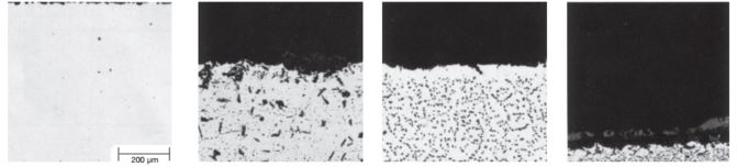
Comparative Burner Rig Oxidation Resistance at 1800°F (980°C)/1000 Hours
(Black areas of micros indicates actual metal loss)
HAYNES® 214® alloy
Average Metal Affected
= 1.8 mils (45.7 µm)
Alloy 601
Average Metal Affected
> 23 mils (> 584 µm)
RA330 alloy
Average Metal Affected
=10.5 mils (267 µm)
Alloy 800H
Average Metal Affected
> 38 mils (> 965 µm)
Comparative Burner Rig Oxidation Resistance at 2000°F (1095°C)/500 Hours
HAYNES® 214® alloy
Average Metal Affected
= 1.2 mils (30 µm)
Alloy 601
Average Metal Affected
> 23 mils (> 584 µm)
RA330 alloy
Average Metal Affected
=17.9 mils (455 µm)
Alloy 800H
Average Metal Affected
> 38 mils (> 965 µm)
Water Vapor
| 1200°F (650°C) | ||||||||
| Alloy |
1008h (cycled weekly) in air + 5%H2O |
1008h (cycled weekly)in air + 10%H2O |
||||||
| Metal Loss* | Average Metal Affected** | Metal Loss* | Average Metal Affected** | |||||
| mils | µm | mils | µm | mils | µm | mils | µm | |
| 214® | 0 | 0 | 0 | 0 | 0 | 0 | 0.08 | 2 |
| 230® | 0 | 0 | 0.05 | 2 | 0.01 | 0 | 0.2 | 5 |
| 625 | 0 | 0 | 0.07 | 2 | 0.01 | 0 | 0.26 | 7 |
| X | 0 | 0 | 0.18 | 4 | 0.01 | 0 | 0.13 | 3 |
| HR‐120® | 0 | 0 | 0.23 | 6 | 0.02 | 0 | 0.55 | 14 |
| 347SS | 0.02 | 0 | 0.28 | 7 | 0.03 | 1 | 0.34 | 9 |
| 253MA | 0.05 | 1 | 0.5 | 13 | 0.08 | 2 | 1.12 | 29 |
| 1400°F (760°C) | ||||||||||||
| Alloy |
1008h (cycled weekly) in air + 5%H2O |
1008h (cycled weekly) in air + 10%H2O |
1008h (cycled weekly) in air + 20%H2O |
|||||||||
| Metal Loss* | Average Metal Affected** | Metal Loss* | Average Metal Affected** | Metal Loss* | Average Metal Affected** | |||||||
| mils | µm | mils | µm | mils | µm | mils | µm | mils | µm | mils | µm | |
| 214® | 0.01 | 1 | 0.05 | 1 | 0.01 | 0 | 0.16 | 4 | 0.01 | 0 | 0.01 | 0 |
| 230® | 0.03 | 1 | 0.24 | 6 | 0.03 | 1 | 0.21 | 6 | 0.04 | 1 | 0.14 | 4 |
| 625 | 0.02 | 1 | 0.13 | 3 | 0.04 | 1 | 0.27 | 7 | 0.05 | 1 | 0.25 | 6 |
| HR‐120® | 0.04 | 1 | 0.24 | 6 | 0.04 | 1 | 0.29 | 7 | 0.08 | 2 | 0.68 | 17 |
| X | 0.04 | 1 | 0.32 | 8 | 0.04 | 1 | 0.3 | 8 | 0.06 | 2 | 0.36 | 9 |
| 617 | – | – | – | – | 0.05 | 1 | 0.45 | 11 | – | – | – | – |
| 253MA | 0.04 | 1 | 0.42 | 11 | 0.08 | 2 | 0.68 | 17 | 0.19 | 5 | 0.99 | 25 |
| 347SS | 0.04 | 1 | 0.46 | 12 | 0.18 | 5 | 0.88 | 22 | 0.78 | 20 | 1.98 | 50 |
| 1600°F (870°C) | ||||||||||||
| Alloy |
1008h (cycled weekly) in air + 5%H2O |
1008h (cycled weekly) in air + 10%H2O |
1008h (cycled weekly) in air + 20%H2O |
|||||||||
| Metal Loss* | Average Metal Affected** | Metal Loss* | Average Metal Affected** | Metal Loss* | Average Metal Affected** | |||||||
| mils | µm | mils | µm | mils | µm | mils | µm | mils | µm | mils | µm | |
| 214® | 0.05 | 1 | 0.21 | 5 | 0.05 | 1 | 0.26 | 7 | 0.04 | 1 | 0.12 | 3 |
| 625 | 0.11 | 3 | 0.41 | 11 | 0.11 | 3 | 0.5 | 12 | 0.11 | 3 | 0.6 | 15 |
| X | 0.09 | 2 | 0.38 | 10 | 0.03 | 1 | 0.5 | 13 | 0.13 | 3 | 1.17 | 30 |
| 230® | 0.06 | 1 | 0.32 | 8 | 0.07 | 2 | 0.53 | 13 | 0.08 | 2 | 1.11 | 28 |
| HR‐120® | 0.08 | 2 | 0.54 | 14 | 0.09 | 2 | 0.68 | 17 | 0.16 | 4 | 1.06 | 27 |
| 617 | – | – | – | – | 0.08 | 2 | 0.88 | 22 | – | – | – | – |
| 347SS | 0.65 | 16 | 1.48 | 38 | 0.86 | 22 | 1.48 | 38 | 7.31 | 186 | 9.34 | 237 |
| 253MA | 0.12 | 3 | 0.43 | 11 | 0.66 | 17 | 1.59 | 41 | 0.64 | 16 | 1.67 | 42 |
| 1800°F (980°C) | ||||||||||||
| Alloy |
1008h (cycled weekly) in air + 5%H2O |
1008h (cycled weekly) in air + 10%H2O |
1008h (cycled weekly) in air + 20%H2O |
|||||||||
| Metal Loss* | Average Metal Affected** | Metal Loss* | Average Metal Affected** | Metal Loss* | Average Metal Affected** | |||||||
| mils | µm | mils | µm | mils | µm | mils | µm | mils | µm | mils | µm | |
| 214® | 0.04 | 1 | 0.24 | 6 | 0.05 | 1 | 0.55 | 14 | 0.04 | 1 | 0.64 | 16 |
| 188 | 0.13 | 3 | 1.43 | 36 | 0.14 | 4 | 1.64 | 42 | 0.18 | 5 | 1.48 | 38 |
| 230® | 0.17 | 4 | 1.47 | 37 | 0.18 | 5 | 1.38 | 35 | 0.19 | 5 | 1.59 | 40 |
| 625 | 0.32 | 8 | 1.62 | 41 | 0.16 | 4 | 1.46 | 37 | 0.36 | 9 | 1.66 | 42 |
| X | 0.27 | 7 | 1.77 | 45 | 0.26 | 7 | 1.66 | 42 | 0.27 | 7 | 1.77 | 45 |
| 556® | – | – | – | – | – | – | – | – | 0.35 | 9 | 1.85 | 47 |
| 617 | 0.3 | 8 | 2 | 51 | 0.15 | 4 | 1.65 | 42 | 0.39 | 10 | 1.99 | 50 |
| HR‐120® | 0.34 | 9 | 1.94 | 49 | 0.36 | 9 | 1.66 | 42 | 0.38 | 10 | 2.08 | 53 |
| 800HT | – | – | – | – | – | – | – | – | 2.47 | 63 | 5.07 | 129 |
| HR-160® | – | – | – | – | – | – | – | – | 0.77 | 20 | 5.57 | 141 |
* Metal loss was calculated from final and initial metal thicknesses; i.e. ML = (OMT – FMT) /2
** Average Metal Affected is sum of Metal Loss and Average Internal Penetration
Carburization Resistance
HAYNES® 214® alloy has very good resistance to carburization, as measured in both packed graphite exposure tests and mixed gas exposure tests. Results for these tests are presented in the following pages. All results are presented in terms of the mass of carbon absorption per unit area, which was obtained from the equation M = C(W/A) where M = the mass of carbon absorption per unit area (mg/cm2). C = difference in carbon (weight fraction) before and after exposure, W = weight of the unexposed specimen (mg) and A = surface area of the specimen exposed to the test environment (cm2).
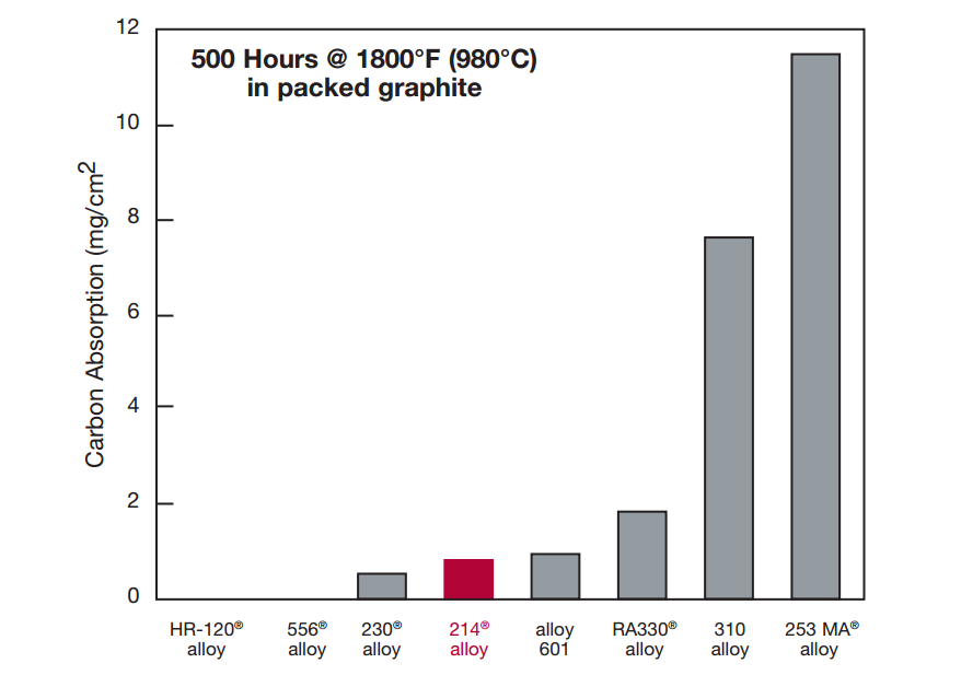
Packed Carburization Resistance
Carbon absorption observed for 214® alloy following 500 hour exposure in packed graphite at 1800°F (980°C) was very low, as shown below. While superior resistance was exhibited by HAYNES HR-120® and 556® alloys, other alloys tested exhibited significantly greater carbon absorption. In particular, the resistance to carburization of 214® alloy was far better than that for the stainless steel type materials.
Mixed Gas Carburization Tests
Carbon absorption observed for 214® alloy following exposure at both 1700°F (925°C) and 1800°F (980°C) to a carburizing gas mixture was significantly lower than that for all other materials tested. This is shown in the graphs on the following pages. For these tests, the exposure was performed in a gas environment consisting of (by volume %) 5.0% H2, 5.0% CO, 5.0% CH4 and the balance argon. The calculated equilibrium composition for the test environments are shown together with the results on the following pages.
Comparative 1700°F (925°C) Mix Gas Carburization Tests
The calculated equilibrium composition (volume %) at 1700°F (925°C) and one atma was 14.2% H2,4.74% CO, 0.0044% CO2, 0.032 CH4 and balance Argon. The activity of Carbon was 1.0 and the partial pressure of Oxygen was 2.47 x 10⁻²² atma.


Comparative 1800°F (980°C) Mixed Gas Carburization Tests
The calculated equilibrium composition (volume %) at 1800°F (980°C) and one atma was 14.2% H2, 4.75% CO, 0.0021% CO2, 0.024% CH4, 0.0098% H2O and balance argon. The activity of Carbon was 1.0 and the partial pressure of Oxygen was 6.78 x 10⁻²² atma.


Resistance to Chlorine-Bearing Environments
HAYNES® 214® alloy provides outstanding resistance to corrosion in high-temperature, chlorinecontaminated oxidizing environments. This is particularly evident for exposures at temperatures at or above 1800°F (980°C), where the formation of the Al2O3-rich protective oxide scale is favored. Test results are shown for 400 hour exposures in a flowing gas mixture of Ar + 20% O2 + 0.25% Cl2. Note that the metal loss exhibited by 214 alloy is very low compared to other alloys tested.

HAYNES® 214® alloy has also been tested in environments with higher levels of chlorine contamination. The photomicrographs to the right are for samples exposed to a mixture of air and 2% chlorine for 50 hours at 1830°F (1000°C). Once again, the black area at the top of each photograph represents actual metal loss experience. Alloy 601 exhibited 2.0 Mils (51 µm) of metal loss, and an average internal penetration of 6.0 Mils (152 µm), for a total average metal affected of 8.0 Mils (203 µm). Results for 214® alloy, by contrast, were 1.0 Mils (25 µm) of metal loss, 1.0 Mils (25 µm) of average internal penetration, for a total average metal affected of only 2.0 Mils (51 µm). These results are consistent with the results for lower chlorine level, longer-term tests given on the previous page.

Nitriding Resistance
While not the most resistant alloy for nitriding environments at traditional 1000°F to 1200°F (540°C to 650°C) temperatures, 214 alloy exhibits outstanding resistance at the higher temperatures where its protective Al2O3 scale can form, even in extremely low oxygen environments. Tests were performed in flowing ammonia at 1200, 1800 and 2000°F (650, 980 and 1095°C) for 168 hours. Nitrogen absorption was determined by technical analysis of samples before and after exposure, and knowledge of the exposed specimen area.
HAYNES® 214® alloy Nitriding Resistance
| Alloy |
Nitrogen Absorption (mg/cm2) |
||
| 1200°F (649°C) | 1800°F (982°C) | 2000°F (1093°C) | |
| 230® | 0.7 | 1.4 | 1.5 |
| 600 | 0.8 | 0.9 | 0.3 |
| 625 | 0.8 | 2.5 | 3.3 |
| 601 | 1.1 | 1.2 | 2.6 |
| 214® | 1.5 | 0.3 | 0.2 |
| X | 1.7 | 3.2 | 3.8 |
| 800H | 4.3 | 4.0 | 5.5 |
| 310 SS | 7.4 | 7.7 | 9.5 |
Physical Properties
| Physical Property | British Units | Metric Units | ||
| Melting Range | 2475-2550°F | – | 1355-1400°C | – |
| Electrical Resistivity | RT | 53.5 µohm-in | RT | 135.9 µohm-cm |
| 200°F | 53.9 µohm-in | 100°C | 136.9 µohm-cm | |
| 400°F | 53.9 µohm-in | 200°C | 136.9 µohm-cm | |
| 600°F | 53.9 µohm-in | 300°C | 136.9 µohm-cm | |
| 800°F | 54.3 µohm-in | 400°C | 137.7 µohm-cm | |
| 1000°F | 54.3 µohm-in | 500°C | 137.9 µohm-cm | |
| 1200°F | 53.5 µohm-in | 600°C | 136.8 µohm-cm | |
| 1400°F | 51.6 µohm-in | 700°C | 133.7 µohm-cm | |
| 1600°F | 49.6 µohm-in | 800°C | 129.2 µohm-cm | |
| 1800°F | 48.0 µohm-in | 900°C | 124.9 µohm-cm | |
| 1900°F | 47.6 µohm-in | 1000°C | 121.6 µohm-cm | |
| 2000°F | 47.6 µohm-in | 1050°C | 120.9 µohm-cm | |
| 2100°F | 48.0 µohm-in | 1100°C | 121.0 µohm-cm | |
| 2200°F | 48.4 µohm-in | 1150°C | 121.9 µohm-cm | |
| - | - | 1200°C | 122.9 µohm-cm | |
| Thermal Conductivity | RT |
83 Btu-in/ft2-hr-°F |
RT | 12.0 W/m-°C |
| 200°F |
88 Btu-in/ft2-hr-°F |
100°C | 12.8 W/m-°C | |
| 400°F |
99 Btu-in/ft2-hr-°F |
200°C | 14.2 W/m-°C | |
| 600°F |
112 Btu-in/ft2-hr-°F |
300°C | 15.9 W/m-°C | |
| 800°F |
132 Btu-in/ft2-hr-°F |
400°C | 18.4 W/m-°C | |
| 1000°F |
153 Btu-in/ft2-hr-°F |
500°C | 21.1 W/m-°C | |
| 1200°F |
175 Btu-in/ft2-hr-°F |
600°C | 23.9 W/m-°C | |
| 1400°F |
200 Btu-in/ft2-hr-°F |
700°C | 26.9 W/m-°C | |
| 1600°F |
215 Btu-in/ft2-hr-°F |
800°C | 29.7 W/m-°C | |
| 1800°F |
225 Btu-in/ft2-hr-°F |
900°C | 31.4 W/m-°C | |
| 2000°F |
234 Btu-in/ft2-hr-°F |
1000°C | 32.7 W/m-°C | |
| 2200°F |
255 Btu-in/ft2-hr-°F |
1100°C | 34.0 W/m-°C | |
| - | - | 1200°C | 36.7 W/m-°C | |
| Thermal Diffusivity | RT |
5.2 x 10⁻³ in2/sec |
RT |
33.6 x 10⁻³ cm2/sec |
| 200ºF |
5.7 x 10⁻³ in2/sec |
100 |
34.5 x 10⁻³ cm2/sec |
|
| 400°F |
6.2 x 10⁻³ in2/sec |
200 |
36.6 x 10⁻³ cm2/sec |
|
| 600°F |
6.8 x 10⁻³ in2/sec |
300 |
39.4 x 10⁻³ cm2/sec |
|
| 800°F |
7.5 x 10⁻³ in2/sec |
400 |
43.2 x 10⁻³ cm2/sec |
|
| 1000°F |
7.9 x 10⁻³ in2/sec |
500 |
47.2 x 10⁻³ cm2/sec |
|
| 1200°F |
8.1 x 10⁻³ in2/sec |
600 |
49.5 x 10⁻³ cm2/sec |
|
| 1400°F |
8.2 x 10⁻³ in2/sec |
700 |
52.9 x 10⁻³ cm2/sec |
|
| 1600°F |
8.4 x 10⁻³ in2/sec |
800 |
51.7 x 10⁻³ cm2/sec |
|
| 1800°F |
9.1 x 10⁻³ in2/sec |
900 |
53.3 x 10⁻³ cm2/sec |
|
| 2000°F |
9.4 x 10⁻³ in2/sec |
1000 |
54.2 x 10⁻³ cm2/sec |
|
| 2175°F |
5.2 x 10⁻³ in2/sec |
1100 |
58.6 x 10⁻³ cm2/sec |
|
| - | - | 1200 |
61.2 x 10⁻³ cm2/sec |
|
| Specific Heat | RT | 0.108 Btu/lb.-°F | RT | 452 J/Kg-°C |
| 200°F | 0.112 Btu/lb.-°F | 100°C | 470 J/Kg-°C | |
| 400°F | 0.118 Btu/lb.-°F | 200°C | 493 J/Kg-°C | |
| 600°F | 0.124 Btu/lb.-°F | 300°C | 515 J/Kg-°C | |
| 800°F | 0.130 Btu/lb.-°F | 400°C | 538 J/Kg-°C | |
| 1000°F | 0.136 Btu/lb.-°F | 500°C | 561 J/Kg-°C | |
| 1200°F | 0.154 Btu/lb.-°F | 600°C | 611 J/Kg-°C | |
| 1400°F | 0.166 Btu/lb.-°F | 700°C | 668 J/Kg-°C | |
| 1600°F | 0.173 Btu/lb.-°F | 800°C | 705 J/Kg-°C | |
| 1800°F | 0.177 Btu/lb.-°F | 900°C | 728 J/Kg-°C | |
| 1900°F | 0.178 Btu/lb.-°F | 1000°C | 742 J/Kg-°C | |
| 2000°F | 0.179 Btu/lb.-°F | 1100°C | 749 J/Kg-°C | |
| 2200°F | 0.180 Btu/lb.-°F | 1200°C | 753 J/Kg-°C | |
| Mean Coefficient of Thermal Expansion | 70 - 400°F | 7.4 µin/in-°F | 25 - 200°C | 13.3 µm/m-°C |
| 70 - 600°F | 7.6 µin/in-°F | 25 - 300°C | 13.6 µm/m-°C | |
| 70 - 800°F | 7.9 µin/in-°F | 25 - 400°C | 14.1 µm/m-°C | |
| 70 - 1000°F | 8.2 µin/in-°F | 25 - 500°C | 14.6 µm/m-°C | |
| 70 - 1200°F | 8.6 µin/in-°F | 25 - 600°C | 15.2 µm/m-°C | |
| 70 - 1400°F | 9.0 µin/in-°F | 25 - 700°C | 15.8 µm/m-°C | |
| 70 - 1600°F | 9.6 µin/in-°F | 25 - 800°C | 16.6 µm/m-°C | |
| 70 - 1800°F | 10.2 µin/in-°F | 25 - 900°C | 17.6 µm/m-°C | |
| 70 - 2000°F | 11.1 µin/in-°F | 25 - 1000°C | 18.6 µm/m-°C | |
| - | - | 25-1100°C | 20.2 µm/m-°C | |
| Dynamic Modulus of Elasticity | RT |
31.6 x 10⁶ psi |
RT | 218 GPa |
| 200°F |
30.6 x 10⁶ psi |
100°C | 210 GPa | |
| 400°F |
29.6 x 10⁶ psi |
200°C | 204 GPa | |
| 600°F |
28.7 x 10⁶ psi |
300°C | 199 GPa | |
| 800°F |
27.4 x 10⁶ psi |
400°C | 190 GPa | |
| 1000°F |
25.3 x 10⁶ psi |
500°C | 184 GPa | |
| 1200°F |
23.9 x 10⁶ psi |
600°C | 177 GPa | |
| 1400°F |
22.3 x 10⁶ psi |
700°C | 170 GPa | |
| 1600°F |
20.2 x 10⁶ psi |
800°C | 162 GPa | |
| 1800°F |
19.0 x 10⁶ psi |
900°C | 151 GPa | |
| - | - | 1000°C | 137 GPa | |
RT = Room Temperature
Tensile Properties
Cold-Rolled and Solution Annealed Sheet, 0.078 to 0.125 Inches (2.0 to 3.2 mm) Thick*
| Test Temperature | Yield Strength at 0.2% Offset | Ultimate Tensile Strength | Elongation | |||
| °F | °C | ksi | MPa | ksi | MPa | % |
| RT | RT | 83.6 | 577 | 141.4 | 975 | 37.3 |
| 1200 | 649 | 77.9 | 537 | 109.6 | 756 | 22.2 |
| 1400 | 760 | 72.3 | 498 | 88.2 | 608 | 20.4 |
| 1600 | 871 | 40.5 | 279 | 49.5 | 341 | 49.4 |
| 1800 | 982 | 6.0 | 41 | 9.8 | 68 | 144.8 |
| 1900 | 1038 | 3.9 | 27 | 7.3 | 51 | 153.1 |
| 2000 | 1093 | 3.0 | 20 | 5.5 | 38 | 157.1 |
| 2100 | 1149 | 2.0 | 14 | 4.0 | 28 | 159.3 |
| 2200 | 1204 | 1.4 | 10 | 3.2 | 22 | 134.6 |
RT= Room Temperature
Hot-Rolled and Solution Annealed Plate, 0.500 Inches (12.7 mm) Thick*
| Test Temperature | Yield Strength at 0.2% Offset | Ultimate Tensile Strength | Elongation | |||
| °F | °C | ksi | MPa | ksi | MPa | % |
| RT | RT | 82.2 | 565 | 138.9 | 960 | 42.8 |
| 1000 | 538 | 71.5 | 495 | 120.0 | 825 | 47.8 |
| 1200 | 649 | 75.9 | 252 | 114.9 | 790 | 33.0 |
| 1400 | 760 | 73.6 | 505 | 94.4 | 670 | 23.1 |
| 1600 | 871 | 50.4 | 345 | 66.4 | 460 | 33.6 |
| 1800 | 982 | 8.4 | 58 | 16.7 | 115 | 86.4 |
| 2000 | 1093 | 4.2 | 29 | 9.0 | 62 | 88.6 |
| 2100 | 1149 | 2.1 | 14 | 6.6 | 46 | 99.4 |
| 2200 | 1204 | 1.4 | 10 | 5.0 | 34 | 91.5 |
RT = Room Temperature
*Elevated temperature tensile tests for plate were performed with a strain rate that is no longer standard. These results were from tests with a strain rate of 0.005 in./in./minute through yield and a crosshead speed of 0.5 in./minute for every inch of reduced test section from yield through failure. The current standard is to use a strain rate of 0.005 in./in./minute though yield and a crosshead speed of 0.05 in./minute for every inch of reduced test section from yield through failure.
Welded Tensile Tests
| Test Temperature | Yield Strength at 0.2% Offset | Ultimate Tensile Strength | Elongation | ||||
| °F | °C | ksi | MPa | ksi | MPa | % | |
| Transverse Specimens with GTAW Welds | RT | RT | 81.0 | 558 | 124.0 | 855 | 22.0 |
| 1000 | 538 | 70.0 | 483 | 99.0 | 683 | 13.0 | |
| 1200 | 649 | 79 | 545 | 97 | 669 | 10 | |
| 1400 | 760 | 77 | 531 | 83 | 572 | 5 | |
| 1500 | 816 | 66 | 455 | 70 | 483 | 5 | |
| 1600 | 871 | 46 | 317 | 50 | 345 | 5 | |
| 1800 | 982 | 10 | 69 | 11 | 76 | 35 | |
| 2000 | 1093 | 4 | 28 | 5 | 34 | 29 | |
| All Weld Metal Specimens | RT | RT | 85 | 586 | 118 | 814 | 33 |
| 1400 | 760 | 81 | 558 | 85 | 586 | 4 | |
| 1500 | 816 | 68 | 469 | 70 | 483 | 4 | |
| 1600 | 871 | N/A | N/A | 51 | 352 | 1 | |
| 1800 | 982 | N/A | N/A | 12 | 83 | 24 | |
Hardness
| Typical ASTM Grain Size | Average Hardness, HRBW | |
| Plate | 3.5 – 5 | 100 |
| Bar | 2.5 – 5.5 | 94 |
| Sheet | 3.5 – 5 | 98 |
Creep and Rupture Properties
Solution Annealed Sheet
| Temperature | Creep | Approximate Initial Stress to Produce Specified Creep in | ||||||||
| 10 h | 100 h | 1,000 h | 10,000 h | |||||||
| °F | °C | % | ksi | MPa | ksi | MPa | ksi | MPa | ksi | MPa |
| 1200 | 649 | 0.5 | – | – | – | – | 46 | 317 | – | – |
| 1 | – | – | – | – | 53 | 365 | – | – | ||
| R | – | – | – | – | 57 | 393 | 37 | 255 | ||
| 1300 | 704 | 0.5 | – | – | 45 | 310 | 30 | 207 | – | – |
| 1 | – | – | 49 | 338 | 32 | 221 | – | – | ||
| R | – | – | 51 | 352 | 33 | 228 | 21* | 145* | ||
| 1400 | 760 | 0.5 | 38 | 262 | 26 | 179 | 17.5 | 121 | 11.2* | 77* |
| 1 | 42 | 290 | 29 | 200 | 18.8 | 130 | 11.7 | 81 | ||
| R | 50 | 345 | 33 | 228 | 19.8 | 137 | 12.3 | 85 | ||
| 1500 | 816 | 0.5 | 23 | 159 | 15 | 103 | 8.9 | 61 | – | – |
| 1 | 27 | 186 | 16.5 | 114 | 9.9 | 68 | – | – | ||
| R | 32 | 221 | 20 | 138 | 11.5 | 79 | 7.0 | 48 | ||
| 1600 | 871 | 0.5 | 12.7 | 88 | 7.5 | 52 | 4.5 | 31 | – | – |
| 1 | 15.2 | 105 | 8.7 | 60 | 4.9 | 34 | – | – | ||
| R | 21* | 145* | 11.8 | 81 | 6.3 | 43 | 3.4 | 23 | ||
| 1700 | 927 | 0.5 | 6.5 | 45 | 3.7 | 26 | 2.1 | 14 | – | – |
| 1 | 7.5 | 52 | 4.2 | 29 | 2.4 | 17 | – | – | ||
| R | 9.8 | 68 | 5.6 | 39 | 3.1 | 21 | 1.8* | 12* | ||
| 1800 | 982 | 0.5 | 1.9 | 13 | 1.2 | 8.3 | 0.75* | 5.2* | – | – |
| 1 | 2.2 | 15 | 1.3 | 9.0 | 0.83* | 5.7* | – | – | ||
| R | 4.8 | 33 | 2.7 | 19 | 1.7 | 12 | 1.0 | 6.9 | ||
| 1900 | 1038 | 0.5 | 1.2 | 8.3 | 0.74* | 5.1* | 0.48* | 3.3* | – | – |
| 1 | 1.4 | 10 | 0.88 | 6.1 | 0.55* | 3.8* | – | – | ||
| R | 3.3* | 23* | 2.0 | 14 | 1.2 | 8.3 | 0.76 | 5.2 | ||
| 2000 | 1093 | 0.5 | 0.75 | 5.2 | 0.55 | 3.8 | 0.32 | 2.2 | – | – |
| 1 | 0.95 | 6.6 | 0.63 | 4.3 | 0.43 | 3.0 | – | – | ||
| R | 2.2* | 15* | 1.5 | 10 | 0.94 | 6.5 | 0.61 | 4.2 | ||
| 2100 | 1149 | 0.5 | 0.53 | 3.7 | 0.35 | 2.4 | – | – | – | – |
| 1 | 0.64 | 4.4 | 0.42 | 2.9 | 0.27 | 1.9 | – | – | ||
| R | 1.6* | 11* | 1.1 | 7.6 | 0.69 | 4.8 | 0.44 | 3.0 | ||
| 2200 | 1204 | 0.5 | – | – | – | – | – | – | – | – |
| 1 | – | – | – | – | – | – | – | – | ||
| R | 1.1* | 7.6* | 0.76 | 5.2 | 0.49 | 3.4 | – | – | ||
*Significant extrapolation
Solution Annealed Plate
HAYNES® 214® alloy - Creep and Rupture Properties
| Temperature | Creep | Approximate Initial Stress to Produce Specified Creep in | ||||||||
| 10 h | 100 h | 1,000 h | 10,000 h | |||||||
| °F | °C | % | ksi | MPa | ksi | MPa | ksi | MPa | ksi | MPa |
| 1400 | 760 | 0.5 | 41* | 283* | 29 | 200 | 21 | 145 | 14* | 97* |
| 1 | 44* | 303* | 32 | 221 | 23 | 159 | 14.5* | 100* | ||
| R | 55* | 379* | 38 | 262 | 24 | 165 | 15.0 | 103 | ||
| 1500 | 816 | 0.5 | 26 | 179 | 19 | 131 | 12.8 | 88 | 7.8* | 54* |
| 1 | 28 | 193 | 20.5 | 141 | 13.8 | 95 | 8.4* | 58* | ||
| R | 35 | 241 | 23 | 159 | 15.0 | 103 | 9.0* | 62* | ||
| 1600 | 871 | 0.5 | 17* | 117* | 11.2 | 77 | 6.2 | 43 | 3.3 | 23 |
| 1 | 20* | 138* | 12.2 | 84 | 6.7 | 46 | 3.7 | 26 | ||
| R | 24* | 165* | 15.0 | 103 | 8.5 | 59 | 4.6 | 32 | ||
| 1700 | 927 | 0.5 | 8.5 | 59 | 4.9 | 34 | 2.6 | 18 | 1.4 | 10 |
| 1 | 9.7 | 67 | 5.3 | 37 | 2.9 | 20 | 1.6 | 11 | ||
| R | 11.5 | 79 | 7.1 | 49 | 4.2 | 29 | 2.4 | 17 | ||
| 1800 | 982 | 0.5 | 2.0 | 14 | 1.3 | 9.0 | 0.85 | 5.9 | – | – |
| 1 | 2.2 | 15 | 1.5 | 10 | 1.00 | 6.9 | 0.68* | 4.7* | ||
| R | 3.9 | 27 | 2.9 | 20 | 1.8 | 12 | 1.1 | 7.6 | ||
| 1900 | 1038 | 0.5 | 1.2 | 8.3 | 0.77 | 5.3 | 0.50 | 3.4 | – | – |
| 1 | 1.4 | 10 | 0.91 | 6.3 | 0.60 | 4.1 | 0.39 | 2.7 | ||
| R | 2.9 | 20 | 1.9 | 13 | 1.2 | 8.3 | 0.8 | 5.5 | ||
| 2000 | 1093 | 0.5 | 0.77 | 5.3 | 0.48 | 3.3 | 0.29 | 2.0 | – | – |
| 1 | 0.93 | 6.4 | 0.62 | 4.3 | 0.41 | 2.8 | 0.20* | 1.4* | ||
| R | 2.1* | 14* | 1.4 | 9.7 | 0.90 | 6.2 | 0.60 | 4.1 | ||
| 2100 | 1149 | 0.5 | 0.47 | 3.2 | 0.27* | 1.9* | – | – | – | – |
| 1 | 0.60* | 4.1* | 0.35 | 2.4 | – | – | – | – | ||
| R | 1.6* | 11* | 1.0 | 6.9 | 0.68 | 4.7 | 0.44 | 3.0 | ||
| 2200 | 1204 | 0.5 | 0.35 | 2.4 | 0.19* | 1.3* | – | – | – | – |
| 1 | 0.45* | 3.1* | 0.26 | 1.8 | – | – | – | – | ||
| R | 1.1* | 7.6* | 0.77 | 5.3 | 0.5 | 3.4 | 0.33 | 2.3 | ||
*Significant extrapolation

Thermal Stability
HAYNES® 214® alloy exhibits reasonable room temperature ductility after longterm thermal exposure at intermediate temperatures. Precipitation of gamma prime phase occurs for exposures below 1750°F (955°C), along with minor chromium-rich carbides. Exposure at temperatures above about 1700°F (925°C) have little effect upon the properties of 214® alloy, but significant grain growth can occur above about 2000°F (1095°C).
Room-Temperature Tensile Properties of Sheet Following Thermal Exposure
| Exposure Temperature | h | 0.2% Offset Yield Strength | Ultimate Tensile Strength | Elongation | |||
| °F | °C | – | ksi | MPa | ksi | MPa | % |
| 1400 | 760 | 0 | 89.4 | 615 | 141.1 | 975 | 37.3 |
| 32 | 104.6 | 720 | 157.5 | 1085 | 27.6 | ||
| 100 | 103.7 | 715 | 157.8 | 1090 | 26.1 | ||
| 1000 | 98.3 | 680 | 156.4 | 1080 | 27.1 | ||
| 1600 | 870 | 0 | 89.4 | 615 | 141.1 | 975 | 37.3 |
| 32 | 81.6 | 565 | 139.7 | 965 | 35.0 | ||
| 100 | 76.9 | 530 | 135.5 | 935 | 35.1 | ||
| 1000 | 71.6 | 495 | 132.5 | 915 | 39.9 | ||
| 1800 | 980 | 0 | 89.4 | 615 | 141.1 | 975 | 37.3 |
| 32 | 84.6 | 585 | 137.5 | 950 | 38.0 | ||
| 100 | 84.7 | 585 | 137.7 | 950 | 34.2 | ||
| 1000 | 87.9 | 605 | 139.6 | 965 | 35.2 | ||
Hot Working
Hot Working
When planning to hot work HAYNES® 214® alloy one should first review the metallurgy of the alloy. With an understanding of its metallurgical characteristics, many options become available to the manufacturer who wishes to hot deform 214® alloy.
Introduction
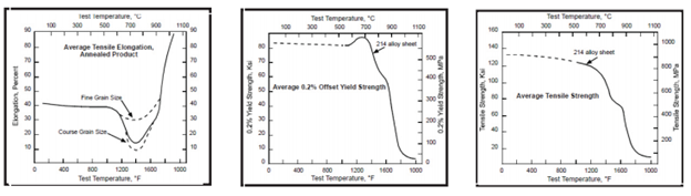
HAYNES® 214® alloy (Ni base; Cr 16; Fe 3; Al 4.5; Y present) is different from most other alloys because it is nickel base and contains aluminum to create its protective alumina surface film. The aluminum also causes the intermetallic compound, Ni3Al, to form rapidly at temperatures between about 1000°F (540°C) and 1750°F (950°C). The intermetallic phase, commonly called gamma prime (γ’), greatly strengthens the alloy, but also reduces the ductility from about 90% tensile elongation near 2000°F (1095°C) to about 15% tensile elongation in the 1300°F (700°C) to 1400°F (760°C) range. This property is shown in the accompanying tensile property graphs.
Grain size of the hot worked part is a function of starting grain size, temperatures of hot working, stress relieving or annealing, and degree or amount of work imparted. In very broad terms, grain size of 214® alloy increases with increasing temperature and is refined by increased working or deformation.
The final grain size of a component is usually important and should be considered when planning forging or other hot working operations. Larger grain sizes tend to yield higher creep and stress rupture life in service, but tend to reduce the intermediate temperature (1200°F (650°C) to 1750°F (950°C)) ductility and increases the tendency of strain age cracking to occur if the component requires welding. Resistance to the environment apparently is not affected by grain size.
Metallurgy
Hot Working Variables HAYNES® 214® alloy has been successfully hot worked in the temperature range of about 2200°F (1200°C) to 1800°F (980°C). Heat up time will vary with size and complexity of the work piece. With complex shapes with transitions from large to small cross sections, it may be beneficial to equilibrate the component at about 1600°F (870°C), before raising the temperature to the final hot working temperature. In general, the best overall results seem to be achieved by working from a furnace temperature near 2100°F (1150°C). Working the alloy quickly with substantial deformation sufficient to maintain heat within the work piece is good practice. Stopping the operation when the work piece reaches 1800°F (980°C) to minimize the chance of cracking caused by the precipitation of gamma prime and the resultant loss of ductility is strongly advised.
If only a modest amount of work is to be done, for example a finishing pass, the operator should consider reducing the furnace temperature to be used for heating the work piece to prevent excessive grain growth in the alloy. Again, stopping the working when the temperature of the piece drops to 1800°F (980°C) is recommended.
Stress Relief and Annealing
As these terms are used here, the difference between stress relieving and annealing is that annealing includes a rapid quench to prevent the precipitation of Ni3Al, whereas a stress relieved part is typically cooled more slowly and provides more uniform cooling. Since the Ni3Al which forms in 214® alloy dissolves (goes into solid solution) at temperatures above about 1800°F (980°C) causing a substantial drop in yield strength, the alloy can be effectively “stress relieved” or solution annealed at temperatures greater than this. It is the usual practice of Haynes International, Inc. to anneal product between 1950-2050°F (1065- 1120°C) and rapidly cool the alloy to prevent, or minimize, the formation of gamma prime if hot deformation processes are complete. If the product is to be subsequently hot deformed, the piece is generally allowed to air cool to ambient temperature after heating.
The actual temperature chosen for stress relief or annealing should be based on the properties desired in the final product. High temperatures tend to yield large grain size, reduced mid-temperature ductility, reduced resistance to strain age cracking, better creep-rupture strengths, lower room temperature strengths, better room temperature ductility and easier machining.
Lower temperatures tend to preserve the existing mid-temperature ductility and grain size, the existing resistance to strain age cracking and result in less distortion, if a quench is used.
When a product is stress relieved and slow cooled, one can expect gamma prime to form in the alloy. This increases room temperature hardness, strength, and difficulty of machining.
The discussions presented here are based upon general experience at Haynes International, Inc., Kokomo, Indiana. They are indicative only of the results obtained at the location and should not be considered as guaranteed operating parameters:
Welding
HAYNES® 214® alloy is a precipitation-strengthened alloy. When the gamma prime phase (Ni3Al) precipitates, the alloy undergoes a slight volumetric contraction. It is possible that stress and strain caused by welding and mechanical deformation caused by the precipitation may cause cracking.
Good welding practice to join gamma prime alloys applies to 214® alloy:
- Base metal should be normally in the solution-annealed condition
- Minimize heat input
- Minimize restraint
- Cleanliness is critical
- Use stringer beads
- Maintain interpass temperature of 200°F maximum
- Use better layers or forgiving fillers (HASTELLOY® X alloy or HASTELLOY® S alloy) as required
- A convex profile (crowned) weld bead is mandatory
- No partial penetration welds
HAYNES® 214® alloy has been joined successfully using gas tungsten arc (GTAW), gas metal arc (GMAW), shielded metal arc (coated electrode), and plasma arc (PAW) welding techniques. Matching composition filler metal is recommended for joining 214 alloy. For shielded metal-arc welding, HASTELLOY® X electrodes (AMS 5799) are suggested. For dissimilar metal joining of 214® alloy to nickel- or cobalt-base materials, HAYNES® 230-W® filler metal will generally be a good selection, but HASTELLOY® S alloy (AMS 5838) or HASTELLOY® W alloy (AMS 5786, 5787) welding products may be used. For dissimilar welding to iron-base materials, HAYNES® 556® (AMS 5831) filler metal is recommended. When using a filler metal other than 214® alloy, the environmental resistances of the weld will be inferior to that of the base metal, and a cover pass using 214® alloy wire is suggested as a means to increase environmental resistance.
Base Metal Preparation
The joint surface and adjacent area should be thoroughly cleaned before welding. All grease, oil, crayon marks, sulfur compounds and other foreign matter should be removed. It is preferable that the alloy be in the solution-annealed condition when welded. One-inch wide areas along each side of the weld joint should be ground to expose bright metal before welding. Welds should also be ground between passes.
Weld Joints
A square butt joint is used for sheet material up to 7/64 inch. A V-joint is used for butt welds in thicknesses from 7/64 inch up to 3/8 inch, a double-V or a U-joint for thicknesses of 3/8 inch to 5/8 inch (a double-V joint is preferred if both sides of the plate are accessible), and a double-U joint for thicknesses over 5/8 inch. T-joints are used when required by design. Partial penetration or fillet welds are not recommended.
V-joints should be beveled to a 60° included angle for GTAW welding, (70° for SMAW), while U-joints should have bevels with an included angle of 30° and a minimum radius of ¼ inch. For coated electrodes, the joint should be opened up an additional 10 – 15°.
Weld Penetration
For full penetration, material 12-gage (7/64 inch) and heavier should be welded from both sides. Material thinner than 12-gage may be welded from one side by using proper edge spacing to allow full penetration. Care should be exercised to prevent incomplete penetration. This condition can leave undesirable crevices and voids in the underside of the joint. Incomplete penetration in material used for high-temperature applications creates stress risers for focal points of mechanical failure.
When welding from both sides is not practical, the joint spacing should be increased and a copper backing bar used. Currents slightly higher than normal are used to obtain complete penetration.
HAYNES® 214® alloy has a lower thermal conductivity than steel; therefore, when using a standard groove, it is necessary to use slightly larger clearance than would be needed for steel.
Preheating, Interpass Temperatures and Postweld Heat Treatment
Preheat is not usually required so long as base metal to be welded is above 32°F (0°C). It is critical to minimize heat input. The lowest amperage and voltage possible are preferred. Minimize weave, use stringer beads when possible. Avoid excessively slow travel speeds and out-of-position welding, which cause heat buildup. Excessively fast travel speeds result in teardrop-shaped weld puddles and should also be avoided to prevent centerline cracking. Interpass temperatures should less than 200°F. Auxiliary cooling methods, including water quenching, may be used between weld passes, as needed, providing that such methods do not introduce contaminants and the part is dried.
Postweld heat treatment for 214® alloy depends on part thickness and complexity. For 214® alloy fabrications that will be in service at 1200-1800ºF, weldments made of greater than 1/4″ thickness, or those which have been welded into configurations which create significant residual stresses, a postweld annealing heat treatment is suggested. The objective of a postweld heat treatment is to minimize and eliminate residual stress in the assembly.
A heat treatment at a metal temperature between 1900ºF and 2000ºF has been successful. The metal at temperature as little as 5 minutes is usually sufficient. If no additional welding or forming is to be performed, the fabrication may be air cooled, otherwise rapid cooling is advised.
Care must be taken when annealing. Heating 214® alloy through the temperature range of 1200-1800ºF will cause gamma prime (Ni3Al) to precipitate. This gamma prime precipitation results in a net shrinkage, as well as an increase in strength and corresponding loss of ductility. In weldments and other highly stressed components, strain-age cracking may occur. This occurs when the residual stresses from forming and welding, augmented by stresses caused by precipitation, exceed the rupture strength of the base metal. It is important to heat the material through the 1200-1800ºF temperature range as rapidly as possible. Do not stress relieve in the 1200-1800ºF temperature range.
Torch heating or heating methods employing direct flame impingement on the fabrication should be avoided. Heating has been successfully done in an air atmosphere, as well as a protective atmosphere.
Disclaimer
Haynes International makes all reasonable efforts to ensure the accuracy and correctness of the data displayed on this site but makes no representations or warranties as to the data’s accuracy, correctness or reliability. All data are for general information only and not for providing design advice. Alloy properties disclosed here are based on work conducted principally by Haynes International, Inc. and occasionally supplemented by information from the open literature and, as such, are indicative only of the results of such tests and should not be considered guaranteed maximums or minimums. It is the responsibility of the user to test specific alloys under actual service conditions to determine their suitability for a particular purpose.
For specific concentrations of elements present in a particular product and a discussion of the potential health affects thereof, refer to the Safety Data Sheets supplied by Haynes International, Inc. All trademarks are owned by Haynes International, Inc., unless otherwise indicated.
Alloy Brochure